Showing posts with label lights. Show all posts

Tuesday, November 18, 2014

Emergency Lights Circuit
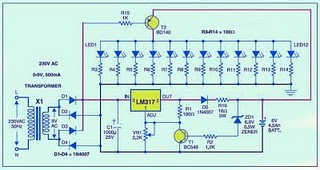
The series of emergency lights on this one is a series of emergency lighting is quite simple and not difficult to make. 

Emergency

Frankly this circuit is not my own design, but at least this series can add to your collection of electronic circuits. The circuit is actually almost the same as the battery charger circuit, its just that in this emergency coupled switching circuit as a circuit breaker when the circuit load is connected to the supply voltage of 220 volts or in other words on the charging position. Meanwhile, when the voltage of 220 volts is lost (PLN lights off), then automatically switches the load switching circuit and turn on emergency lights, where the supply that is used is derived from batteries that have been installed in stand-by position.

In a series of emergencies over the use of LED as a lighting load emergency. And indeed these days we find a lot of emergency lights that are sold in the market that use LEDs, but the LED is used instead led carelessly but has led a gleam of light. The advantages of the use of this led the led is very efficient because once will consume battery power so that with a limited supply to run the series in a long time.

Circuit components used for emergency lighting is not too much, and indeed the components used are the components that are commonly used as components for circuit switching power supply and battery charging. IC LM 317 ic regulator is useful as a producer of supply voltage to supply the batteries. Transistor T2 (BD 140) is useful as switching, ie, decide the flow toward the load at 220 volts PLN lamp life so that lighting will be extinguished. But when the lights PLN did not provide the supply voltage of the transistor T2 will connect the connection from the battery to the load light.

Components used:
Resistors: R1 (180 uhm), R2 (1.2 K), sd R3 R14 (100 ohms), R15 (1 K) and R16 (16 ohm, 5 watt)
Capacitors: C1 (1000 UF)
Diodes: D1 until D5 (IN 4007)
Transistors: T1 (BC 548) and T2 (BD 140)
Zener Diodes 6.8 Volt
IC: LM 317
Battery charger
Transformer
If you are not happy using this type of charger with IC LM317 series like the example above then you can use another type of charger circuit that you think is more appropriate and can work optimally. Then you simply add the switching function by using one or more transistors.
Read More..

Thursday, November 13, 2014

LM339 based Grand Prix Starting Lights circuit

This circuit reproduces the starting light sequence currently used by FISA for Formula One racing. It could be used with slot car sets (such as HO scale AFX/Life Like/Tyco sets) or radio controlled cars. IC1, a 555 timer IC, is used as a clock pulse generator. Its output is fed via NAND gates IC2a and IC2c to IC3, a 4024 binary counter. IC2b inverts the O4 output of 4024 binary counter IC3. Initially, IC3 is reset and all its outputs are low, including O4, which causes IC2b to present a logical high to the pin 8 input of IC2c which then passes pulses from the 555 clock circuit to the clock input of the 4024. IC3 then begins counting.

After the count has reached binary 1111, the next pulse sends the O4 output of IC3 high, which disables IC2c and IC3 stops counting. The four used outputs of IC3 are connected to a resistor ‘ladder’ which acts as a simple digital to analog convert-er (DAC). As the count increases so does the voltage produced at the top of the ladder and this is connected to the inverting inputs of four comparators inside IC4 (an LM339) and to IC5, which is a 741 op amp also connected as a comparator.

The positive inputs of the comparators are connected to the taps of a voltage divider, with the tapping voltages set using VR1, a 100kO trimpot. As IC3 counts, the rising stepped voltage from the DAC ladder switches the comparators on in sequence, starting with IC4d and working up to IC5. As each comparator is turned on, its pair of LEDs is lit; first LEDs 1 & 2, then LEDs 3 & 4 and so on. When all five pairs of LEDs are lit, the next pulse from IC1 moves the binary count of IC3 to 10000, so the DAC voltage drops back to zero and all LEDs are extinguished. At the same time, counting also stops, because the high on O4 causes IC2c to block further gate pulses. The circuit then remains inactive until the counter is reset by pressing pushbutton switch S1. This allows a new sequence to begin.
Author: David Richards – Copyright: Silicon Chip Electronics
Source:http://www.extremecircuits.net/2010/06/grand-prix-starting-lights_12.html

Read More..

Monday, August 25, 2014

Simple Flashing Lights Schematic

This is a simple flashing lights schema can be used as beacon. The assembly consists basically of two blinking steps that commands two light bulbs. With the help of P1 you can adjust the flashing frequency between some limits. There are 2 parts for the schema, the second one works the same way as the other but with the help of a wire bridge or a switch you can choose different operating modes.A bridge between M and 3 means: 2 independent blinks.

Circuit diagram :
Flashing

Flashing Lights Schematic Circuit Diagram

If there is a bridge between M and 2, then the lamps lights alternatively with a frequency that can be adjusted with P1. And finally there is one more possibility for M and 1, where the lamps blinks at the same time. The flashing lights schema works with voltages between 3V and 15V. The lamps voltage must be 2/3 of working voltage. R5 and R10 are chosen so that the lamps are about to light.
Read More..

Friday, August 22, 2014

Emergency Lights Circuit

The series of emergency lights on this one is a series of emergency lighting is quite simple and not difficult to make. 

Emergency

Frankly this circuit is not my own design, but at least this series can add to your collection of electronic circuits. The circuit is actually almost the same as the battery charger circuit, its just that in this emergency coupled switching circuit as a circuit breaker when the circuit load is connected to the supply voltage of 220 volts or in other words on the charging position. Meanwhile, when the voltage of 220 volts is lost (PLN lights off), then automatically switches the load switching circuit and turn on emergency lights, where the supply that is used is derived from batteries that have been installed in stand-by position.

In a series of emergencies over the use of LED as a lighting load emergency. And indeed these days we find a lot of emergency lights that are sold in the market that use LEDs, but the LED is used instead led carelessly but has led a gleam of light. The advantages of the use of this led the led is very efficient because once will consume battery power so that with a limited supply to run the series in a long time.

Circuit components used for emergency lighting is not too much, and indeed the components used are the components that are commonly used as components for circuit switching power supply and battery charging. IC LM 317 ic regulator is useful as a producer of supply voltage to supply the batteries. Transistor T2 (BD 140) is useful as switching, ie, decide the flow toward the load at 220 volts PLN lamp life so that lighting will be extinguished. But when the lights PLN did not provide the supply voltage of the transistor T2 will connect the connection from the battery to the load light.

Components used:
Resistors: R1 (180 uhm), R2 (1.2 K), sd R3 R14 (100 ohms), R15 (1 K) and R16 (16 ohm, 5 watt)
Capacitors: C1 (1000 UF)
Diodes: D1 until D5 (IN 4007)
Transistors: T1 (BC 548) and T2 (BD 140)
Zener Diodes 6.8 Volt
IC: LM 317
Battery charger
Transformer
If you are not happy using this type of charger with IC LM317 series like the example above then you can use another type of charger circuit that you think is more appropriate and can work optimally. Then you simply add the switching function by using one or more transistors.
Read More..