Friday, December 12, 2014

Battery Charger for NiCad Batt

charger

This battery charger circuit is designed for recharging NiCad batteries based on an AC-powered current source method.It can crank out as much as 1 amp and can be modified to go even higher by choosing different devices for Q1. Since this circuit uses AC line voltages and currents, please exercise extreme caution during assembly, turn-on, and test. 
Read More..

Wireless Transmitter for IR Headphone

This circuit shows a Wireless Transmitter for IR Headphone.
Read More..

Dual Voltage Inverter

This voltage inverter schematic can produce a dual (positive and negative) voltage from a single supply input.It is therefore extremely useful for powering opamp and other circuits that require a dual voltage from a single battery. The circuit will operate at an input voltage from around 5V to 20V and produce a output from +-2.5V to +-10V. 
Read More..

Thursday, December 11, 2014

Car Laptop Power Supply Adaptor

laptop-adaptor-schematic
The laptop adaptor described here plugs into a car cigarette lighter socket and produces a 19V nominal output voltage adjustable by + - 0.5V. The input voltage range is from 9.2V to 15V and the output voltage shows good regulation even with large fluctuations of the input voltage. 
Read More..

Thursday, November 20, 2014

1 Lamp with 2 switches

Series 1 light 2 switch configuration is intended to control lights from two locations arefar apart. Application of series 1 light with 2 switches are often implemented in thehallway or tunnel. In the application in a hallway or tunnel, with a series like this we can turn on or turn off the light from each tunnel or hallway door. The number of lights can bereproduced by paralleling. The circuit is very simple because only built of 1 and 2pieces of fruit lamp selector switch. If you want to use a lamp with a power greater then the switch can be replaced with 1 piece contactor (relay) for each switch. Then switchused to turn on and turn off the relay replacement S1 and S2.

The working principle with 2 series 1 light switch is the light will light when the S1 and S2 different position, and the lights will be on at the time of the switch position S1 and S2 together. In the installation of switches S1 and S2 each put at the end of the hallway or tunnel.
Read More..

Mini Amplifier with 3 Transistor

Mini 3 transistor amplifier is a simple amplifier with 50mW power drawn by 3 transitor.
The series of three mini-amplifier transistors can be used for loud speaker 8 ohm load. Source voltage required to activate the mini-amplifier can be drawn from the batteries 9V.Rangkaian 3 transistor amplifier is often used in simple portabe audio devices such as radios or small tape recorder. Mini-transistor amplifier circuit 3 is quite simple as shown in the figure below.


Mini


Mini-transistor amplifier circuit 3 includes type of amplifier OTL (Output Transformer Less). Mini-transistor amplifier circuit 3 is used for output coupling capacitors. Amplifier circuit is simple and suitable when used for audio amplifier experiment.
Read More..

Improving Performance Bass Amplifier

Stereo power amplifier is less in the bass tones, but if a speaker that sounds just feels solid bass sound, there are several possibilities, the first one speaker cable upside down, try alternating bass and tone tests.
If still, you need to use 2 power supply or attempting to use this circuit. Note this circuit works for a power amp that is less power transformer with 2 speakers (stereo). One of the speaker cable (output) should be reversed, this is okay, just a game to lighten the work phase transformer from the blow bass.

We recommend that before you try this circuit, turn one speaker cable and a second test speakers with bass tones, the bass should be mutually reduce (bass-bass = 0). Next remove the driver from boknya and turn the speakers (the speaker drivers facing into the wall), the bass should grow (bass + bass = 2bass). One record store in the town of Indramayu is taking this simple way, certainly looks magnet speakers, great.

The heart of this circuit using IC with 2 op-amps, can type JRC4558, LF353, TL072, TL082, and similar. Vcc = + /-70Vdc. If Vcc = + /-42Vdc, replace the value of R9 and R10 to 2K2.
Op-amp 1 functions as a buffer, while the op-amp to-2 function as inverting the phase 180 , both have a reinforcement of 1 times.

Improving

Improving

List of components:
R1, 2,5,6 .......... 100K
R3, 4 ................ 2K2
R7 ................... 100
R9, 10 .............. 2K2-3K3
C1, 2 ............... 100uf/25V
D1, 2 ............... 15V Zener
IC1 ................. TL072
Read More..

Wednesday, November 19, 2014

TDA 7012T FM Radio Receiver

FM Radio Receiver IC TDA 7012T is very simple, but it has an FM radio receiver sensitivity and good selectivity. Single Chip FM Receifer cool name of IC TDA7012T 7012T TDA is to build an FM receiver requires a few additional components. Feature contained in FM receiver IC TDA 7012T is quite tempting to an FM receiver. Among features an FM receiver TDA 7012T is a low-voltage applications micro affability arrangement (MTS), Frequency Loked Loop (FLL) to 76 KHz range and selectivity of FM receiver with RC Filter. In an article by FM Radio Receiver IC TDA 7012T can be seen in the FM receiver circuit which can be made​​.
 
Image Series FM Radio Receiver with IC TDA 7012T


From the picture above components to make the FM Radio Receiver IC TDA 7012T as follows:

R1 = 8kΩ2
R2 = 10kΩ
R3 = 390Ω
C1, C3 = 10nF
C2, C6, C9, C16 = 100nF
C4 = 33pF
C5 = 25pF trimmer
C7, C10 = 1nF5
C8 = 820pF C11 = 1NF
C12 = 68pF
C13 = 220pF
C14 = 47μF 10V
C15 = 3nF3
L1 = 36nH
L2 = 1μH,
IC1 = TDA7021T

Hopefully useful and become an idea in the manufacture of Mini FM Receiver with IC TDA 7012T
Read More..

Programming Learning MCS51

Learning Programming MCS51 becomes mandatory we learn if we want to use the MCS51. In the first part of this Learning Programming MCS51 we will learn together about the basic programming language MCS51 microcontroller. Where to program MCS51 outline there are 2 core parts of pemrogramanya language is "Words Work" and "Object". In the article Programming MCS51 this first part we will study first the "verb" is a command group Peng-copies of data, the command group arithmetic and logic command group.

Programming
Reference to DATA IN PROGRAMMING MCS51
Data can be in many different places, thus known a few ways to describe the data (in English often referred to as Addressing Mode), among others, as follows:

The mention of constant data (immediate addressing mode): MOV A, # $ 20. Constant data is data that was in the instructions. Examples of this instruction has the data meaning a constant $ 20 (as a constant data marked with #) on-copy it into the accumulator A. What needs to be properly addressed in this order is the number $ 20 is part of the instruction.
Reference to data directly (direct addressing mode), this method is used to refer to data residing in memory by calling the memory number where the data are: MOV A, $ 30. Examples of these instructions have the meaning of data in the memory number $ 30 in-copy it to the accumulators.
At first glance these same instructions to the instruction constant data above, the difference above instructions using the # which marks the $ 20 is a data constant, whereas in this instruction because there was no sign # then $ 30 is a number from memory.

The mention of indirect data (indirect addressing mode), this method is used to refer to data residing in memory, if memory data storage is changing its location so that the memory number is not called directly but in-titip her into another register : MOV A, @ R0.
In this instruction versatile R0 register is used to record the number of memory, so that this instruction has a memory meaning that the number recorded in the contents of R0-copy it into the accumulator A.

Sign @ is used to mark the memory number stored in R0.

Compare this with the instruction memory number directly mention above, in this instruction first memory numbers are stored in R0 and R0 appoint a role which memory is used, so that if the value of R0 change the designated memory will also be changed as well.

In this instruction registers R0 functioning multipurpose container for the address register (indirect address register), other than all-purpose registers R0 R1 can also be used as a container for the address register.

Reference to data in the register (register addressing mode): MOV A, R5. This instruction has the meaning of data in all-purpose register R5 is copy it into the accumulator A. This instruction makes all-purpose registers R0 to R7 as a place to store data that is very practical that it works very fast.
The data referred to in the discussion above all in the data memory (including all-purpose registers are also located in data memory). In writing the program, often required standard table that is stored along with the program. Tables of this kind is really a data residing in program memory!
For this purpose, MCS51 have any mention of data in memory means programs conducted by indirect (indirect addressing code mode): MOVC A, @ A + DPTR.

Notice in this MOV instruction is replaced with MOVC, the additional letter C is meant to distinguish that this instruction is used in the program memory. (MOV without the letter C means that the instruction used in the data memory).

Sign @ is used to mark A + DPTR is used to indicate the number of contents in-memory copy it to the accumulator A, in this case the value stored in the DPTR (Data Pointer Register - 2 bytes) plus the value stored in accumulators A (1 byte) is used to refer to the program memory numbers.

Verb in AT89Cx051
Overall AT89Cx051 have as many as 255 kinds of instruction, which was formed by combining the verb and objects. "The verb is the group discussed the following:

PENG GROUP-COPY-DATA AN MCS51
Basic code for this group are MOV, abbreviation of MOVE, which means to move, though more correct to say this command have meaning copying the data. This can be explained the following: after the instruction MOV A, R7 done, accumulators A and all-purpose register R7 contains the same data, originally stored in R7.

MOV command is distinguished according to the type of memory AT89Cx051. This command is on the memory data is written into MOV, for example:


MOV A, $ 20

MOV A, @ R1

MOV A, P1

MOV P3, A

To use the program memory, this command is written into MOVC, there are only 2 types of wear MOVC instructions, namely:


MOVC A, @ A + DPTR; DPTR as register indirect

MOVC A, @ A + PC, PC as the register indirect


In addition, there is also known MOVX command, the command that is used for external data memory (X singkatakan from External). This command is only available to the MCS51 family members who have an external data memory, for example AT89C51 and so forth, and certainly not known by the group that tidam AT89Cx051 have external data memory. There are only 6 kinds of wear MOVX instruction, these instructions are:


MOVX A, @ DPTR

MOVX A, @ R0

MOVX A, @ R1

MOVX @ DPTR, A

MOVX @ R0, A

MOVX @ R1, A


GROUP ARIMATIK (ADD, ADDC, SubB, DA, MUL and DIV)
ADD and ADDC command

The contents of accumulators A plus the number 1 byte, the sum will be collected back in the accumulator. In this operation Carry bit (C flag in the PSW - Program Status Word) serves as a reservoir overflow of the sum. If the sum of the abundance (a value greater than 255) will carry bit value 1 , if not Carry bit value 0. ADDC same with ADD, only in bits Carry ADDC value in the previous process involved summed together.

Numbers 1 byte is added to the accumulator, can be derived from a constant, from the all-purpose register, memory data from memory number is called directly or indirectly, as shown in the following example:

ADD A, R0; register versatile

ADD A, # $ 23; a constant

ADD A, @ R0; no memory indirect

ADD A, P1; no direct memory (port 1)


ORDERS IN PROGRAMMING SubB MCS51
The contents of Accumulator A less the number 1 byte follows with Carry bit value, the reduction will be accommodated again in the accumulators. Carry bits in this operation also serves as a reservoir overflow of the reduction. If the reduction is abundant (score less than 0) bits Carry would be worth 1 , if not Carry bit value 0.

SubB A, R0; A = A - R0 - C

SubB A, # $ 23; A = A - $ 23

SubB A, @ R1

SubB A, P0


DA command

DA command (Decimal Adjust) is used after the command ADD, ADDC, or SubB, used to convert 8-bit binary value stored in the accumulator into 2 pieces decimal number, each consisting of 4-bit binary value.

MUL AB ORDERS IN PROGRAMMING MCS51
8-bit binary number in accumulator A is multiplied by an 8-bit binary number in register B. The result of multiplication of binary 16-bit, 8 bit binary number that greater weight be accommodated in the register B, while the other 8 bits are accommodated in the smaller weight accumulator A.

OV bit in the PSW (Program Status Word) is used to mark the result of multiplying the existing value in register B. OV bit will be worth 0 if register B is worth $ 00, if not worth OV bit 1.

MOV A, # 10

MOV B, # 20

MUL AB

DIV AB ORDERS IN PROGRAMMING MCS51
8-bit binary number in accumulator A is divided by an 8-bit binary number in register B. The result of the division of 8-bit binary numbers stored in the accumulator, while the rest of the division of 8-bit binary number stored in register B.

OV bit in the PSW (Program Status Word) is used to mark the value before the division that exists in the register B. OV bit will be worth 1 if register B originally worth $ 00.

GROUP LOGIC (ANL, ORL and XRL) IN PROGRAMMING MCS51
This command group used to perform logic operations MCS51 microcontroller, logic operations can be done is the AND operation (operation code ANL), OR operation (operation code ORL) and the Exclusive-OR operation (XRL operation code).

The data used in this operation can be data that is in the accumulator or data that are in-memory data, this is a little different with arithmetic operations that must be actively melihatkan accumulators.

Operating results are accommodated in the first data source.

AND logic operation is widely used to me 0 a few specific bits of an 8-bit binary number, the way to forming an 8-bit binary numbers as a data-ANL constant in a number of origin. Bit-0 want in a represented by 0 in constant data, while other bits given the value 1, eg
Instructions ANL P1, #% 01111110 will result in bit 0 and bit 7 of Port 1 (P1) value 0 while the other bits remain unchanged in value.

OR logic operation is widely used to me 1 a few specific bits of an 8-bit binary number, the way to forming an 8-bit binary numbers as constant data in a number-ORL origin. Bit-1 want in a represented by 1 in constant data, while other bits given the value 0, eg
Instructions ORL A, #% 01111110 will result in bit 1 to bit 6 of the accumulator value 1 while other bits remain unchanged in value.

Exclusive-OR logic operation is widely used to reverse the value (complement) some particular bits of an 8-bit binary number, the way to forming an 8-bit binary numbers as constant data in a number-XRL origin. Bit you want behind-the value represented by 1 in constant data, while other bits are the value 0, eg
Instructions XRL A, #% 01111110 will result in bit 1 to bit 6 of the accumulator turned value, while other bits remain unchanged in value.
Read More..

Adjustable Switching Regulator Circuit with LM2576

The Adjustable Switching Regulator Circuit with LM2576 are monolithic integrated circuits that provide all the active functions for a step-down (buck) switching regulator, capable of driving 3A load with excellent line and load regulation. These devices are available in fixed output voltages of 3.3V, 5V, 12V, 15V, and an adjustable output version.
LM2576 IC Package
Requiring a minimum number of external components, these regulators are simple to use and include internal frequency compensation and a fixed-frequency oscillator. The Adjustable Switching Regulator Circuit with LM2576 offers a high-efficiency replacement for popular three-terminal linear regulators. It substantially reduces the size of the heat sink, and in some cases no heat sink is required.


IC Switching Regulator Circuit with LM2576

A standard Adjustable Switching Regulator Circuit with LM2576 of inductors optimized for use with the LM2576 are available from several different manufacturers. This feature greatly simplifies the design of switch-mode power supplies.

Other features include a guaranteed ±4% tolerance on output voltage within specified input voltages and output load conditions, and ±10% on the oscillator frequency. External shutdown is included, featuring 50 μA (typical) standby current. The output switch includes cycle-by-cycle current limiting, as well as thermal shutdown for full protection under fault conditions.

Features Adjustable Switching Regulator Circuit with LM2576 :
- 3.3V, 5V, 12V, 15V, and adjustable output versions
- Adjustable version output voltage range,1.23V to 37V
- Guaranteed 3A output current
- Wide input voltage range, 40V up to 60V for HV version
- Requires only 4 external components
- 52 kHz fixed frequency internal oscillator
- TTL shutdown capability, low power standby mode
- High efficiency
- Uses readily available standard inductors
- Thermal shutdown and current limit protection
- P+ Product Enhancement tested
Read More..

Tuesday, November 18, 2014

Simple fm transmitter for the experiment

Simple fm transmitter for the experiment. This designation may be appropriate to call this series, because rangkaianya very simple and suitable for learning / beginners. and preferably when assembling, which assembled its first part oscilator. then we try it first. if able to function normally, we can proceed to the next level up to the booster.


Read More..

Solid State Relay Circuit

Solid state relay is a series of hibryd that serves as a mechanical relay. Solid state relays is built with insulating an MOC to separate the input and the switch. Solid state relay with us to avoid the occurrence of sparks as it does on conventional relays can also avoid the occurrence of the connection is not perfect because the porous contactor as in conventional relays. Solid state relay circuit is quite simple and we can make in a PCB hole. For more details can be seen in the picture following a series of solid state relays.


Solid state relay has many advantages including no mechanical friction on the contactor, the connection process only occur when there are crosses zero, there is no spark at the contactor, not noisy, small consumtion flow control, better endurance.
Read More..

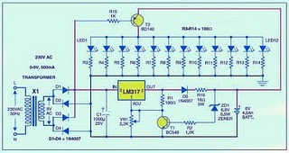
Emergency Lights Circuit

The series of emergency lights on this one is a series of emergency lighting is quite simple and not difficult to make. 

Emergency

Frankly this circuit is not my own design, but at least this series can add to your collection of electronic circuits. The circuit is actually almost the same as the battery charger circuit, its just that in this emergency coupled switching circuit as a circuit breaker when the circuit load is connected to the supply voltage of 220 volts or in other words on the charging position. Meanwhile, when the voltage of 220 volts is lost (PLN lights off), then automatically switches the load switching circuit and turn on emergency lights, where the supply that is used is derived from batteries that have been installed in stand-by position.

In a series of emergencies over the use of LED as a lighting load emergency. And indeed these days we find a lot of emergency lights that are sold in the market that use LEDs, but the LED is used instead led carelessly but has led a gleam of light. The advantages of the use of this led the led is very efficient because once will consume battery power so that with a limited supply to run the series in a long time.

Circuit components used for emergency lighting is not too much, and indeed the components used are the components that are commonly used as components for circuit switching power supply and battery charging. IC LM 317 ic regulator is useful as a producer of supply voltage to supply the batteries. Transistor T2 (BD 140) is useful as switching, ie, decide the flow toward the load at 220 volts PLN lamp life so that lighting will be extinguished. But when the lights PLN did not provide the supply voltage of the transistor T2 will connect the connection from the battery to the load light.

Components used:
Resistors: R1 (180 uhm), R2 (1.2 K), sd R3 R14 (100 ohms), R15 (1 K) and R16 (16 ohm, 5 watt)
Capacitors: C1 (1000 UF)
Diodes: D1 until D5 (IN 4007)
Transistors: T1 (BC 548) and T2 (BD 140)
Zener Diodes 6.8 Volt
IC: LM 317
Battery charger
Transformer
If you are not happy using this type of charger with IC LM317 series like the example above then you can use another type of charger circuit that you think is more appropriate and can work optimally. Then you simply add the switching function by using one or more transistors.
Read More..

POWER SUPPLAY 13 8 Volt Schematic

POWER
POWER
POWER
POWER

Part list for 12 Amp BDX33-based power supply:

  • 2 x 15 volt 6+ amps

  • 2 times two MR750 (MR7510) diodes (MR750 = 6 Ampere diode) or 2 times 3 1N5401 (1N5408) diodes.

  • F1 = 1 Amp

  • F2 = 15 amp

  • R1 2k2 1 Watt

  • R2 10k

  • R3 1k 0.5 watt

  • R4,R5,R6,R7 0.1 ohm 10 watt

  • R8 4.7

  • R9 6k8

  • C1 two times 4700uF/35v

  • C2 330uF/35v

  • C0,C3,C4,C6,C10 100nF

  • C7 330uF/25v

  • C8 47nF

  • C9 47uF/25v

  • D1 1N5401

  • D2 LED

  • D3, D4, D5 1N4001

  • IC1 78L15

  • relay 12 volt 2x5 amp switching

  • 3 darlington transistors: T0,T1,T2 = BDX-33 NPN TO-220 transistor

  • Zd 8 or 9 volt, 5 watt

  • P1 2k trimmer

If using a bridge rectifier (like in schematic 2) you do not need 2 x 15 volts 6 amps, but 1 x 15 volt 10+ Amps

Part list for 20 Amp BDX33-based power supply:

  • 2 x 15 volt 12+ amps

  • 2 times 3 MR750 (MR7510) diodes (MR750 = 6 Ampere diode) or 2 times 5 1N5401 (1N5408) diodes.

  • F1 = 2 Amp

  • F2 = 25 amp

  • R1 2k2 1 Watt

  • R2 10k

  • R3 1k 0.5 watt

  • R4,R5,R6,R7 0.1 ohm 10 watt

  • R8 4.7

  • R9 6k8

  • C1 22000uF/35v

  • C2 330uF/35v

  • C0,C3,C4,C6,C10 100nF

  • C7 330uF/25v

  • C8 47nF

  • C9 47uF/25v

  • D1 1N5401

  • D2 LED

  • D3, D4, D5 1N4001

  • IC1 7815

  • relay 12 volt 10 amp switching

  • Four darlington transistors: T0,T1,T2,T3 = BDX-33 NPN TO-220 transistor

  • Zd 8 or 9 volt, 5 watt

  • P1 2k trimmer

If using a bridge rectifier (like in schematic 2) you do not need 2 x 15 volts 12 amps, but 1 x 15 volt 20 Amps

Read More..

Monday, November 17, 2014

Boster 15 watt rd 15 no tune

15 rd booster requires only 0.5 watts of input capable of out 15 watts, the voltage of 13.8 volts it needs. in this series are made to work freq 87-108 mhz fm broadcast. but did not rule to be modified in other freq. schematic and pcb layout to please download here


Read More..

Radio Control for toy car

play toy cars controlled by radio signals is an interesting game. The much-loved toy cars children, plus a simple circuit would be ideal for toy cars. This series of families use traditional digital CMOS IC which requires a very small electric current, so it does not impose on the performance of the original toy cars.
In this system, radio signals emitted not continuously but only generated when the controller sends a command left / right or forward / backward, and even then only a radio frequency of an intermittent, so it is sending pulses of radio wave frequency.

Number of pulses sent represents a command is sent, the command GO is represented by 8 pulses, represented by 16 pulses LEFT, RIGHT DOWN 32 pulses and 64 pulses. Command sent to a combination of two orders once gus, which is a combination of command forward / backward and right / left, for example, could be sent forward command and left once gus, in this case the number of pulses sent is 24, which is the sum of the forward command command as much as 8 pulses and left as many as 16 pulses.
Once a command is sent, the system stops sending commands in a certain time lag, the lag time it takes the receiver circuit will have sufficient time to execute properly. Frequency pulses were visible on the right side of Figure 1.

How it works The transmitter
Radio signals generated by the oscillator circuit formed by transistors Q1 9016, the working frequency of the oscillator is determined by the crystal Y1 is worth 27.145 MHz. A very critical part of this oscillator circuit is T1, L1 and L2, which specifically dealt with separately at the end of this article.
Work of the oscillator is controlled by a NOR gate U2D 14001, while the output gate (pin 3) is worth 1 , the oscillator will work and transmit radio frequency 27.145 MHz, and at the output U2D value 0 the oscillator will stop working.
U2D NOR gate receives the clock signal from the NOR gates U2B. NOR gate CMOS type with the help of resistors R4 and R5 and capacitor C8 to form a low frequency oscillator circuit to control the clock shaper of existing digital circuits. Working from the clock generator is controlled via the input leg 6, the circuit will generate the input clock that is berlevel 0 .
NOR gate U2A and U2C form a latch circuit (RS Flip Flop), due to the influence of resistor R2 and capacitor C11 which is fed to pin 9 on U2C, when the circuit gets power supply output U2C must be 1 and U2A output (pin 3) to 0 . This situation resulted EUIS clock generator generating a clock U2B work and release the reset state of the enumerator 14 024 IC (U1), so that the U1 start chopping and 27.145 MHz oscillator circuit to send pulses of the clock generator frequency during work.
At the start chopping, all the output IC 14 024 enumerators in kedaan 0 , after chopping the 8 pulse output Q4 (pin 6) will be 1, after chopping 16 Q5 pulse output (pin 5) to 1 , after chopping 32 Q6 output pulse (pin 4) to 1 , after 64 counts pulses output Q7 (pin 3) to 1.
Outputs are used to control the voltage above 9 feet U2C through diode D1 and D2, as long as it remains one of the output value 0 then the plant U2B clock still works, it will continue until dankatode D2 D1 cathode to 1 so that the foot 9 U2C a 1 as well. This situation will lead to 3 feet U2A output to 1 , which stops the clock generator and reset U2B enumerator 14 024 danberhenti is sending pulses of frequency 27 145 MHz.
To generate the lag time for the receiver circuits have enough time to perform the command, used a series of 9014 Q2, the resistor R7 and capacitor C10. The magnitude of the delay time is determined by the value of R7 and C10. The switch to send the command forward / backward and to send the command left / right are two separate switches. Each switch has three positions, the center position means that the scalar does not send commands.
How It Works Recipients
Figure 2 is a recipient of a series of paired images dimobil toy, serves to receive signals from the transmitter to control the motor cars, so cars can move forward / backward and left / right. Transistor Q1 with the help of resistors; capacitors and T1 form as a series of 27.145 MHz radio signal receiver. T1 in series with a T1 is exactly the same used in the transmitter circuit, how to make it are discussed below.
Transistor Q2 perlangkapannya formed following a series of pulses to change the radio frequency received from the transmitter into the box pulses that can be accepted as a digital signal by the CMOS IC. Digital signal will be received as the clock had to be chopped by enumerator 14 024 IC (U2). Output of 14 024 would correspond to the number of pulses sent by the transmitter, forward command and left (which is used as an example in the discussion of the transmitter) is the pulse number of 24, the enumeration of these pulses resulted in 14 024 to be output Q4 = 1 , Q5 = 1, Q6 = 0 and Q7 = 0.
The received digital signal other than U2 used as counter clock IC 14 024 discussed above, is also used to move the 3 pieces of the time delay circuit to generate pulses which controls the sequence of work.
The first control pulse will appear after submission frequency pulse stopped because the lag time between sending the code, this pulse count function to record the results of 14 024 to 14 042 U3 (D Flip Flop), so that the final condition of 14 024 will be retained to control the motor. After the results were recorded for 14 024 14 042, 14 042 counter is reset by the second pulse, so that after the lag time counter counts up starting from 14 042 to 0 again.
Circuit formed by transistors Q3, Q4, Q7, Q8, Q9 and Q10 H Bridge is named as a series, this series is very powerful to drive the DC motor. With this circuit the DC motor can be rotated to the right-to-left or stop motion. The main requirement is the use of this circuit Q7 and the base voltage of Q10 base voltage must be opposed, for example, the base Q7 = 1 and the base of Q10 = 0 motor rotates to the left, the base of Q7 = 0 and the base of Q10 = 1 motor will turning to the right, the base Q7 = 0 and Q10 base = 0 motor stop motion, but should not be happening base Q7 = 1 and the base Q10 = 1.
Similarly, Q5, Q6, Q11, Q12, Q13 and Q14 form an H Bridge. H Bridge to the left in Figure 2 is used to control a motor that regulates the movement of cars left / right, while the H Bridge to the right is used to control a motor that regulates the movement forward / backward cars.
The relationship between outpur enumerator 14 042 and input D Flip Flop 14 024 is arranged such that the signal is fed to each of the H Bridge can not be all 1 simultaneously.


Manufacture of transformer TX and RX
Transformer T1 in the series transmitter and receiver, is the same stuff, and have made ​​themselves. Transformer was built using a plastic transformer Koker (spare part radio) that has a step that appears 5 lines that can be filled with coils of wire, as shown in the photograph. Wearing this Koker facilitate wire transformer windings. Otherwise it could be similar Koker, just the usual wear. Koker is a small transformer and feritnya also small (3 mm) as that used to be used for the assembly of CB 27 MHz radio.
Can wear a wire to wire the transformer in the unloading of Koker, carefully open coil of wire that already exist in the Koker because the wire is quite smooth and quite easy to break.
Step 1: rolls of wire which is numbered 5 feet to 4 feet in the direction of h (CW) for 3 rolls right on level 1 (pathway level above the bottom line)
Step 2: Roll the wire from 1 foot to 2 feet in a clockwise direction as much as 4 rolls right on level 2.
Step 3: Continue the roll (from step 2) in a clockwise direction as much as three quarter roll to 3 feet on three levels. (Can be determined exactly a quarter of the roll, because it has a track kokernya split into 4).
Manufacture of coil L1
Roll of copper wire diameter from 0.3 to 0.5 mm by 10 quarter rolls on Koker diameter of about 4 mm (which will be released) is also in a clockwise direction.
Manufacture of coil L2
Roll of copper wire 0.1 mm diameter by 50 rolls in plastic Koker without ferrite diameter of about 3.5 - 4 mm (look for the plastic material from scrap) is also in a clockwise direction. Long section on liputi rolls along the 5 mm.
Read More..

Complete Home theater set up speakers

Home theaters are getting to be extremely popular among American homes. This modern technology is slowly giving movie theaters a run for their money. Basic knowledge of home theater system and its basic components may be best for people who want to bring home relaxation and entertainment. 

The most important consideration in the design and complete set up of your home theater is the size of the room. The home theater speakers and the other components of your home theater may need to consider the size of the room. Too small rooms for your home theater may not require so many speakers. Only three speakers may be good if the room is quite small. 

Do not overload your small room; you may not be able to get the entertainment and relation you want if you feel overloaded with so many home theater speakers. Because you only need three home theater speakers in your small room, you may need to acquire the high-end brand of home theater speakers to compliment the size of the room and the other equipments for your home theater.

Complete home theater speaker setup
If you have a bigger room however, the basic three home theater speakers may not be enough. You may need to put up to six speakers around the room, you may also consider complimenting your home theater speakers with subwoofer to complete the surround sound like in movie theaters. In addition to the speakers, you may also need to purchase a high-end television set which should not be smaller than 27 inches. It may not be reasonable if you buy a smaller television set because it may drown in the fineness of your home theater speakers.


Additionally, the DVD player needs to be of high quality, having progressive scan your DVD Player may help provide sharp images and flicker-free pictures for your home theater system. The home theater speakers, television and DVD player are the basic components of a home theater system especially if the room is quite small. However, for bigger room, adding home theater furniture and home theater projectors may be necessary to complete the package. Again, it may be worth it, if your home theater speakers are of high quality. This is because of the need to provide a surround sound for the home theater set up. The DVD player and the television set may answer for the requirement of sight in a movie theater setup. Your home theater speaker needs to answer for the sound requirement, and if your home theater speaker is not of high quality brand, it may not be able to do the job for you.

In order for you to avoid making mistakes in your choice of home theater equipments including home theater speakers, and home theater furniture, you may require the services of a home theater designer. They will be able to provide the best recommendation that will ensure you will get the most out of your home theater system including topnotch home theater speakers. Additional home theater furniture may be necessary to complete the package and to dress up the whole room. Since they are the designers, they will be able to recommend the best for your home theater system set up. If you have a properly designed home theater, you will be the best entertainment possible.

Your home theater designer may take on the huge responsibility of choosing the most suitable home theater speaker to attain the best design for your home theater.

Bring home relaxation and entertainment right in your own living room, home theater system can provide this to you and your family.
Read More..

Sunday, November 16, 2014

Diode recovery time

Understanding the parameters of "diode recovery time" .For prospective technicians are still learning and inexperienced, they generally recognize only two kinds of parameters of a diode, namely:

  • The maximum working voltage (bias voltage when he gets back - or when not deliver - or when "off")
  • The maximum operating current (when he gets a forward bias voltage of - or as leads - or when "on")
Fast Recovery diodes
A similar experience we had some twenty years ago when a new SMPS first introduced on the television. When there is a diode voltage B + is broken. And then we replace the diode from the outside (our point of diode being sold in stores, rather than the official service) diode turns hot and soon broken. We think that the replacement diode voltage or current is less bulky. Then after replacement with a larger, but the result remains the same damage. Finally we order the diode with the same part number, and when the part arrived and was installed wrong results immediately.

Then why the diode is purchased in the market is hot and faulty? Actually there are many other parameters that have a diode. One more thing to be understood by a technician is called a "diode recovery time".
Common diode rectifier is used for the power supply circuits of 50Hz, when he gets forward biased diode voltage will deliver ("on"). Then, if the bias voltage is turned upside down then the diode does not turn into leads ("off"). If the diode is then mounted on a high-frequency ac voltage. So when given the diode forward bias voltage will deliver ("on") as usual. But when the bias voltage is turned upside down, apparently indirect diode can turn into "off" quickly. 

There is a delay of a minute to "off" so that when the bias voltage is turned "off" there is still a bit of reverse leakage current. If the frequency of the ac leakage current was further compounded the greater the return. Reverse leakage current is what causes the diode to be hot.
Diode recovery time is a parameter of a diode which shows the "time" needed for the change of position "on" to "off" position. The smaller the value the better the recovery time is used at high frequencies.


Based on the parameters of the diode recovery time, then this type of diode is classified into:
  • Diode general, for the rectifier AC voltage
  • Fast Recovery Diode, used in the circuit and the flyback SMPS with a frequency of approximately 35 Khz
  • Super Fast recovery diode, used in SMPS circuits with a frequency of about 70 to 80 Khz.
  • Tips to find the diode equation.
  • If we can not get the diode with the same part number, then we will usually replace it with another part number. We will replace the diode with the diode used in the same location. For example, diode B +-A model of the television is broken, then we will replace the B + diode that is used by television B or C.
Read More..

Digital Volt Meter Circuit

Digital volt meter circuit is simple and not much use of additional components. Volt meter circuit uses IC L7107 as a main actor. L7107 IC is an Analog to Digital Converter (ADC) which has been equipped with the viewer seven segment driver 3 1 / 2 digits. IC L7107 in the application of digital volt meter is in it has been equipped with an internal voltage reference circuit, analog switches, sequential control logic, and LED display driver. This digital meter volt circuit can be operated with a working voltage 5VDC. A full suite of digital volt meter can be seen in the following figure.

Digital

To set or Calibration to 0 Volt. done by adjusting the VR 2KOhm. then to test the display can be done by pressing the test switch, where to normal conditions when the switch is pressed then all the display lights up.
Read More..

Saturday, November 15, 2014

POWER FAILURE ALARM

This minuscule power failure alarm circuit is a power supply monitoring device that will set off a piezo-speaker when the ac mains mains supply cuts off. It is very helpful to indicate the loss of power supply to some power-critical instruments such as a lifecare device installed in a hospital. Alarm activation at the right time is helpful as it signals that there is a power outage and urgent action should taken to recover the situation by providing an alternative power supply.
This is a 9V battery operated, low component count, and light weight circuit which can be safely connected to any AC230V outlet. At its heart is the famed little timer chip LM555 (IC1) configured as an astable multivibrator. Another important component is the “home-baked” opto-coupler (PC1). No bulky power transformer is used here, hence the circuit is “noise-free” (no electromagnetic interference). Further, this makes the enfolding task very simple!


Although a variety of opto-couplers are available in the market but it may so happen that you may not have one ready at hand when you get a spark and want to check the idea as soon as possible. Fortunately, it is easy to construct one at home using an LED and a phototransistor/photo resistor. Just take a small piece of common circuit board and solder the components as indicated here. Keep an eye on the spacing of the components; it should be as close as possible with a slight gap between them. In the prorotype one 5mm white LED + 5mm LDR combination was used. After the construction, enclose the optocoupler in a suitable opaque tube, or cover the whole unit using short-length of heatshrink tube.


The circuit is straight forward. As stated, IC1 is here wired as a gated-astable producing an audio-frequency (AF) output (~1KHz) to drive a standard ordinary/piezo-speaker. Switching of the astable is controlled by the power status detection circuitry built around PC1 and associated components. Switch S1 (SPST) is the system on/off switch, and LED2 (5mm Red) is an optional visual indicator.


Parts List 

IC1 : LM555
T1 : BC547
T2 : BD139
D1 : 1N4007
LED1 : White 5mm
LED 2 : Red 5mm
R1 : 100K
R2 : 5mm LDR
R3 : 1K
R4 : 10K
R5,R6 : 4K7
R7,R8 : 1K
C1,C2 : 100nF
C3 : 470uF/16V
S1 : SPST switch
BATT : 9V battery
SPKR : Ordinary/Piezo-Speaker (not active buzzer)

Read More..

Friday, November 14, 2014

VOLTMETER USING 8051 MICROCONTROLLER

A simple 0-5V voltmeter using 8051 is shown in this article. This digital voltmeter has a sensitivity of  200mV which is a bit low but this project is meant for demonstrating how an ADC and seven segment display can be interfaced to 8051 to obtain a digital readout of the input voltage. A 31/2 digit high end voltmeter will be added soon. ADC0804 is the ADC and AT89S51 is the controller used in this project.
a


About the Circuit

In the circuit Vref/2 (pin9) of the ADC is left open and it means that the input voltage span can be o to 5V and the step size will be 5/255 = 19.6mV. The equation for the digital output of ADC0804 is Dout = Vin/Step size. In this circuit, for an input voltage of 1V the digital output will be 1/19.6mV = 51 and so the binary equivalent of 51 ie 00110011. Digital output of the ADC is interfaced to P1.0 of the microcontroller. Control signals for the ADC ie CS, RD, WR and INTR are available from the P3.7, P3.6, P3.5 and P3.4  pins of the microcontroller respectively. 2 digit multiplexed seven segment display is interfaced to Port0 of the microcontroller. Control signals for the display driver transistors Q1 and Q2 are obtained from P3.2 and P3.1 of the microcontroller. Push button switch S1, capacitor C2 and resistor R10 forms a debouncing reset circuitry. 

Program

ORG 00H
MOV P1,#11111111B
MOV P0,#00000000B
MOV P3,#00000000B
MOV DPTR,#LABEL
MAIN : CLR P3.7
       SETB P3.6
       CLR P3.5
       SETB P3.5
WAIT : JB P3.4,WAIT
       CLR P3.7
       CLR P3.6
       MOV A,P1
       MOV B,#10D
       DIV AB
       MOV B,#2D
       MUL AB
       MOV B,#10D
       DIV AB
       SETB P3.2
       ACALL DISPLAY
       MOV P0,A
       ACALL DELAY
       MOV P0,#10000000B
       ACALL DELAY
       MOV A,B
       CLR P3.2
       SETB P3.1
       ACALL DISPLAY
       MOV P0,A
       ACALL DELAY
       CLR P3.1
       SJMP MAIN
DELAY : MOV R3,#02H
DEL1 : MOV R2,#0FAH
DEL2 : DJNZ R2,DEL2
       DJNZ R3,DEL1
       RET
DISPLAY : MOVC A,@A+DPTR
          RET
LABEL : DB 3FH
        DB 06H
        DB 5BH
        DB 4FH
        DB 66H
        DB 6DH
        DB 7DH
        DB 07H
        DB 7FH
        DB 6FH
END

About the Program

At first the program controls the ADC to produce a digital output corresponding to the input voltage.This digital output is scanned through P1.0 and is loaded to accumulator. Then the value in the accumulator is divided by 10 to omit the last digit. For example, let the input voltage be 4V. Then the corresponding  digital output of the ADC will be  204D (D stands for decimal) .After  the the division by 10, the value left in the accumulator will be 20D. This 20D is then multiplied by 2D which results in 40D. The next target of the program is to manipulate this 40D and make a 4.0 readout on the display. For this the 40D is again divided by 10D . This results in 4 inside accumulator and 0 inside B register. Then the program gets the digit drive pattern for 4 using the lookup table , puts this pattern on Port 0 and activates Q1. After 1 ms delay 10000000B is loaded to P0 and this accounts for the dot. After a further 1ms delay Q1 is deactivated, content in B (ie 0) is moved to A, gets the correct digit drive pattern for 0 using the lookup table, puts this pattern on Port 0 and activates Q2. After a further 1ms delay Q2 is deactivated and the entire cycle is repeated.
Read More..

Thursday, November 13, 2014

AC Ohmmeter ESR Meter The ESR Meter is basically an AC Ohmmeter with special scales and protective circuitry It provides a continuous reading of s

The ESR Meter is basically an AC Ohmmeter with special scales and protective circuitry. It provides a continuous reading of series resistance in electrolytic capacitors. It operates at 100 kHz to keep the capacitive reactance factor near zero. The remaining series resistance is due to the electrolyte between the capacitor plates and indicates the state of dryness. Capacitor termination problems also show up plainly due to the continuous ohmic reading.

The ESR meter uses 8 operational ainplifiers. An op-amp is an idealized basic amplifier with two inputs. The non-inverting input (+) has an in-phase relationship with the op-amp output, and the inverting input (-) an out-of-phase relationship. Op-amps are usually used with negative feedback and reach a stable operating condition when their two inputs are equal in voltage.

Op-amps IA & 1B form a regenerative 100 kHz oscillatnr circuit. Capacitor C1 is the basic tiining capacitor and RI is selected to set frequency. Diodes D2 & D3 clip the bottom and top of the output waveform so that the output level and frequency are resistant to battery voltage changes.

The oscillator output of op-amp 1B drives 10-ohm source resistor R8F. The test-capacitor, thru the test leads, couples this 100 kllz signal to 10-ohm load resistor R9F. The amount of voltage developed here is indicative of the capacitors ESR value. (The 10-ohm resistors determine the basic iieter scaling.)

Capacitor C3 blocks any DC voltage present on the test-capacitor. Diodes D4 & D5 protect the ESR Meter from any initial charging current to C3. Resistor R7 discharges C3 after test.

A DC operating bias of 0.55 V is established by diode D1 for the oscillator stage and for all subsequent stages, which are DCcoupled and operated class A. DC bias from D1 and ESR signal from R9F are combined at the input of op-amp 1D. Both voltages are amplified by 1D, 1C, & 2A. Each of these three stages has an amplification factor of about 2.8 due to the ratio of output-voltage to feedback~voltage at the (-) input, which is determined -by feedback resistors R13F & R14F, etc.

Op-amp 2D is configured as a peak-to-peak detector. when the in-corning AC signal goes more positive than the normal bias level of about 0.77 Volt, the output of 2D also goes positive. But it must go positive enough to overcome the voltage drop across diode D6 before a fully equalizing positive voltage can be fed back to the -(-) input thru R20 to stabilize the op-amp.

-Capacitor C4 is charged to the peak value of the AC signal and accurately represents the peak of the incoming AC signal. The voltage drop across the diode becomes almost inconsequential due to the feedback process, and the circuit works down to a few mV.

A similar action occurs during the negative peak, using D7 & C5.

Resistor R21 provides a constant minimum amount of negative feed--back around op-amp 2D. The negative feedback increases the op-amp bandwidth which, most importantly, keeps the amplifier input-to-output phase-shift low enough for proper circuit operation.

The two outputs from the peak-to-peak detector are connected to two high-input-impedance unity-gain DC amplifiers, which drive the 1 mA meter movement differentially. 
Read More..

LM339 based Grand Prix Starting Lights circuit

This circuit reproduces the starting light sequence currently used by FISA for Formula One racing. It could be used with slot car sets (such as HO scale AFX/Life Like/Tyco sets) or radio controlled cars. IC1, a 555 timer IC, is used as a clock pulse generator. Its output is fed via NAND gates IC2a and IC2c to IC3, a 4024 binary counter. IC2b inverts the O4 output of 4024 binary counter IC3. Initially, IC3 is reset and all its outputs are low, including O4, which causes IC2b to present a logical high to the pin 8 input of IC2c which then passes pulses from the 555 clock circuit to the clock input of the 4024. IC3 then begins counting.

After the count has reached binary 1111, the next pulse sends the O4 output of IC3 high, which disables IC2c and IC3 stops counting. The four used outputs of IC3 are connected to a resistor ‘ladder’ which acts as a simple digital to analog convert-er (DAC). As the count increases so does the voltage produced at the top of the ladder and this is connected to the inverting inputs of four comparators inside IC4 (an LM339) and to IC5, which is a 741 op amp also connected as a comparator.

The positive inputs of the comparators are connected to the taps of a voltage divider, with the tapping voltages set using VR1, a 100kO trimpot. As IC3 counts, the rising stepped voltage from the DAC ladder switches the comparators on in sequence, starting with IC4d and working up to IC5. As each comparator is turned on, its pair of LEDs is lit; first LEDs 1 & 2, then LEDs 3 & 4 and so on. When all five pairs of LEDs are lit, the next pulse from IC1 moves the binary count of IC3 to 10000, so the DAC voltage drops back to zero and all LEDs are extinguished. At the same time, counting also stops, because the high on O4 causes IC2c to block further gate pulses. The circuit then remains inactive until the counter is reset by pressing pushbutton switch S1. This allows a new sequence to begin.
Author: David Richards – Copyright: Silicon Chip Electronics
Source:http://www.extremecircuits.net/2010/06/grand-prix-starting-lights_12.html

Read More..

Simple Circuit Diagram for Amplifier by TDA7052

This is a very small and simple Circuit Diagram for Amplifier of 1W mono audio output. The amplifier is based on a single IC TDA7052. It is in 8-pin DIL (Dual-In-Line) package. The IC TDA7052 is specially designed for battery-operated audio circuit for amplifier like tape recorders, radios etc.

Circuit Diagram of Simple 1W Audio Amplifier:

Simple
Fig: Simple Circuit Diagram for Amplifier
The power supply for this amplifier is 3V to 12V, but we recommend to use 6V power supply. If you want to going with battery, no problem the amplifier can also operate by even 3V Battery cell . The IC TDA7052 no needed any Heat Sink. In the circuit R2 is a Variable Resistor, used as volume controller. Capacitor C1&C2 used to filtering the supply voltage. If battery is used instead of power supply then it(C1&C2) isn’t needed anymore in the circuit. Use an 8Ω speaker at the output to hearing the mono amplification of audio. 
Read More..

Wednesday, November 12, 2014

Descrete Multistage Light Sequencer

The drawing below illustrates a multistage light sequencer using descrete parts and no integrated circuits. The idea is not new and I hear a similar circuit was developed about 40 years ago using germanium transistors. The idea is to connect the lights so that as one turns off it causes the next to turn on, and so forth. This is accomplished with a large capacitor between each stage that charges when a stage turns off and supplies base current to the next transistor, thus turning it on. Any number of stages can be used and the drawing below illustrates 3 small Christmas lights running at about 5 volts and 200mA. The circuit may need to be manually started when power is applied. To start it, connect a momentary short across any one of the capacitors and then remove the short. You could use a manual push button to do this. 

Detailed operation:
Assume the circuit doesnt start when power is applied amd all lights are off and all three capacitors are charged to about 5 volts. We connect a jumper across the 220uF capacitor on the left which discharges the capacitor and turns on the 2nd stage transistor and corresponding light. When the jumper is removed, the capacitor will start charging through the base of the stage 2 transistor and stage 1 light. 
This causes the stage 2 transistor to remain on while the capacitor continues to charge. At the same time, the capacitor connecting stage 2 and 3 will discharge through the 100 ohm resistor and diode and stage 2 transistor. When the capacitor charging current falls below what is needed to keep stage 2 turned on, the transistor and light will turn off causing the voltage at the collector of the stage 2 transistor to rise to 5 volts. 
Since the capacitor connecting stage 2 and 3 has discharged and the voltage rises at the collector of stage 2, the capacitor from stage 2 and 3 will charge causing the 3rd stage to turn on and the cycle repeats for sucessive stages 4,5,6,7.... and back to 1. The sequence rate is determined by the capacitor and resistor values (220uF and 100 ohms in this case), load current (200mA in this case), and current gain of the particular transistor used. This arrangement runs at about 120 complete cycles per minute for 3 lights, or about 167mS per light. Faster or slower rates can be obtained with different capacitor values. 
Read More..

RTS0072B Voice changer circuit project with Diagram Circuit

A very simple voice changer electronic circuit project can be designed using the RTS0072B single chip CMOS LSI designed for voice changer, which can transpose or distort one voice into another voice by encoding the input audio signals in normal speed and transmit the output audio signals with unusual speed. That is accomplished by sampling the input audio signals into digital signals and re-arranges the digital signals to generate different voice from the user normal voice.
This circuit project is very simple and require few external electronic parts . Circuit must be powered from a DC power supply circuit that will provide a fixed output voltage between 3 and 5 volts .
This circuit has various voice effects like transposing voice (higher or lower) ,amplifying voice and robot voice .
As you can see in this project is used a 9 volts DC power supply , because this circuit uses a LM386 audio amplifier IC that will amplify the output signal .
Read More..

Adjustment power supply values 1 25 15V Max current 0 5 amp

This is power supply that have Voltage output fine the value has 1.25-15V. From by Output current that be valuable about 0.5 amp that 12V and 0.2 amp that 15V.
When Volt , from 220V houses reach transformer. It will modify Volt 220V to be 18VAC already to change rectifier circuit. Which D1, D2, C1 and R1 wasp be Full wave rectifier circuit. For modify DCV to ACV to a signal DCV. It make get a signal DCV that have voltage at pin 3 of IC1 be 20V. From that time DCV signal this reach fight DC Regulator circuit. Which use IC number LM317. This circuit will perform to maintain one’s position Voltage smoothly. Which level output voltage at get this will go out the way pin 2 of IC1. By have capacitors C2 be voltage filter in order that voltage output level of the circuit is will high class modify to follow fining. The performing fee withstands VR1 there.

Read More..

Tuesday, November 11, 2014

TDA1151 based Motor Speed Controller circuit with explanation

This motor speed controller uses a TDA1151 monolithic integrated circuit , designed by ST Microelectronics . TDA1151 motor speed controller circuit is designed in a SOT-32 plastic package and can be used for small applications where the space inside is very critical .
Also this circuit diagram can be used as speed regulator for DC motors of record players, tape and cassette recorders, movie cameras, toys or other low cost applications.

This speed controller circuit can provide a high output current up to 800 mA without any additional components and has a low quiescent current of 1.7mA .
The TDA1151 require a low reference voltage ( around 1.2 volts ) and it has a excellent parameters stability versus temperature .
The maximum voltage that can be applied to the TDA1151 is around 20 volts .
As you can see in the circuit diagram the TDA1151 require just few common external components and is very easy to design .

Source: electroniq.net

Read More..

Sunday, November 9, 2014

Input Impedance Booster II

The input resistance of a.c.-coupled op amp circuits depends almost entirely on the resistance with which the d.c. setting is determined. If CMOS op amps are used, the input resistance is normally high, currently up to 10 MΩ. If a higher value is needed, a bootstrap circuit may be used. This enables the input resistance to be boosted artificially to a very high value, indeed In the circuit shown in the diagram, resistor R1 sets the d.c. point for IC1a. The terminal of the resistor linked to pin 7 of IC1 would normally be at earth potential, so that the input impedance would be 10 MΩ. Connecting the other terminal of the resistor to earth via IC1a and network C2-R3-R2 as far as d.c. is concerned results in the requisite d.c. setting of the op amp.


As far as alternating voltages are concerned, the input signal is fed back so that only a tiny alternating current flows through R1. Therefore, Rin=R1[(R2+R3)/R3]. With resistor values as specified, Rin is about 1 GΩ. One aspect must be borne in mind: the numerical value of (R2+R3)/R3 must not exceed 0.99. This means that the value of R3 cannot be less than 100 kΩ if the value of R2 is 10 MΩ. If these conditions are not met, the circuit will become unstable. 
Read More..

Saturday, November 8, 2014

Efficient Fan Speed Controller

A partial solution to quietening noisy PCs can be to reduce the speed of internal cooling fans. Low-cost fan speed controllers are available, but they often employ inefficient, heat-generating linear regulators and contain no temperature feedback mechanism. This idea makes use of a readily available, cheap in-car mobile phone charger. The majority of these use common circuitry and require only minor modifications to operate as efficient fan speed controllers complete with temperature feedback. Most in-car chargers are based on the well-known MC34063 DC-DC switchmode IC.

When used for charging mobile phones, the open-circuit output voltage is typically set to between 7V and 9V. This is achieved with a simple voltage divider across the output, the centre point of which connects to the feedback input (pin 5) of the MC34063. To make the output voltage var-iable with air temperature, first replace the upper resistor of the divider with a 4.7kΩ resistor in series with a 4.7kΩ trimpot. The lower half of the divider is then replaced with a 470Ω resistor in series with a 500Ω NTC thermistor. These values are only a guide and can be varied to suit different thermistor and fan types.


Efficient Fan Speed Controller Circuit Diagram

Note that component lead length should be minimised to avoid introducing noise into the feedback circuitry. Getting the correct fan starting voltage is a matter of trial and error. The values shown on the circuit give a starting voltage of about 6.8V at room temperature but trimpot VR1 can be used to raise this voltage as necessary. The output can then rise to about 10V if the interior temperature rises sufficiently. The 4.7kΩ resistor could be reduced to 3.9kΩ and VR1 adjusted to give a lower starting voltage if the fan speed is still too high at 7V. After running for one hour or so, the fan voltage as set by the interior case temperature thermistor on my PC settled at 7.4V.

Suitable chargers are available from Oatley Electronics, Cat. No. 2D0074. They’re currently listed at $5 for two, which is less than the price of the MC34063 ICs alone! Data on the MC34063 can be downloaded from www.onsemi.com and a useful development aid is to be found at www.nomad.ee/micros/mc34063. Finally, note that not all chargers have an output filter capacitor installed. Typically, this is a 220µF 10V or 16V electrolytic type. To save a few cents, the manufacturers sometimes leave this component out, relying on the mobile’s battery to perform the filtering task. If this component is missing from your charger’s PC board, it should be installed before the supply is used.
Read More..