Thursday, December 11, 2014
Car Laptop Power Supply Adaptor

Tuesday, November 18, 2014
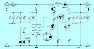
POWER SUPPLAY 13 8 Volt Schematic
Part list for 12 Amp BDX33-based power supply:
2 x 15 volt 6+ amps
2 times two MR750 (MR7510) diodes (MR750 = 6 Ampere diode) or 2 times 3 1N5401 (1N5408) diodes.
F1 = 1 Amp
F2 = 15 amp
R1 2k2 1 Watt
R2 10k
R3 1k 0.5 watt
R4,R5,R6,R7 0.1 ohm 10 watt
R8 4.7
R9 6k8
C1 two times 4700uF/35v
C2 330uF/35v
C0,C3,C4,C6,C10 100nF
C7 330uF/25v
C8 47nF
C9 47uF/25v
D1 1N5401
D2 LED
D3, D4, D5 1N4001
IC1 78L15
relay 12 volt 2x5 amp switching
3 darlington transistors: T0,T1,T2 = BDX-33 NPN TO-220 transistor
Zd 8 or 9 volt, 5 watt
P1 2k trimmer
If using a bridge rectifier (like in schematic 2) you do not need 2 x 15 volts 6 amps, but 1 x 15 volt 10+ Amps
Part list for 20 Amp BDX33-based power supply:
2 x 15 volt 12+ amps
2 times 3 MR750 (MR7510) diodes (MR750 = 6 Ampere diode) or 2 times 5 1N5401 (1N5408) diodes.
F1 = 2 Amp
F2 = 25 amp
R1 2k2 1 Watt
R2 10k
R3 1k 0.5 watt
R4,R5,R6,R7 0.1 ohm 10 watt
R8 4.7
R9 6k8
C1 22000uF/35v
C2 330uF/35v
C0,C3,C4,C6,C10 100nF
C7 330uF/25v
C8 47nF
C9 47uF/25v
D1 1N5401
D2 LED
D3, D4, D5 1N4001
IC1 7815
relay 12 volt 10 amp switching
Four darlington transistors: T0,T1,T2,T3 = BDX-33 NPN TO-220 transistor
Zd 8 or 9 volt, 5 watt
P1 2k trimmer
If using a bridge rectifier (like in schematic 2) you do not need 2 x 15 volts 12 amps, but 1 x 15 volt 20 Amps
Saturday, November 15, 2014
POWER FAILURE ALARM


Parts List
Wednesday, November 12, 2014
Adjustment power supply values 1 25 15V Max current 0 5 amp
This is power supply that have Voltage output fine the value has 1.25-15V. From by Output current that be valuable about 0.5 amp that 12V and 0.2 amp that 15V.
When Volt , from 220V houses reach transformer. It will modify Volt 220V to be 18VAC already to change rectifier circuit. Which D1, D2, C1 and R1 wasp be Full wave rectifier circuit. For modify DCV to ACV to a signal DCV. It make get a signal DCV that have voltage at pin 3 of IC1 be 20V. From that time DCV signal this reach fight DC Regulator circuit. Which use IC number LM317. This circuit will perform to maintain one’s position Voltage smoothly. Which level output voltage at get this will go out the way pin 2 of IC1. By have capacitors C2 be voltage filter in order that voltage output level of the circuit is will high class modify to follow fining. The performing fee withstands VR1 there.
Friday, November 7, 2014
9 Volt Power Supply Circuit Diagram Using IC 7809

- If a current of 300 mA or above is required, fit a proper heat sink to the IC 7809.
- If 1A bridge is not available, make one using four 1N 4007 diodes.
Wednesday, November 5, 2014
Car Bulb Power Flasher
Devices of this kind are particularly suited for road, traffic and yard alerts and in all cases where mains supply is not available but a powerful flashing light is yet necessary.
| Parts | Description |
| R1 | 6.8K |
| R2 | 220K |
| R3 | 22K |
| C1 | 100uF-25V |
| C2 | 10u-25V |
| D1 | 1N4002 |
| Q1 | BC557 |
| Q2 | IRF530 |
| LP1 | 12V-21W Car Filament Bulb (See Notes) |
| SW1 | SPST Switch (3 Amp minimum) |
- Flashing frequency can be varied within a limited range by changing C1 value.
- As high dc currents are involved, please use suitably sized cables for battery and bulb(s) connections.
Thursday, October 30, 2014
AC Power Amplifier with Simplified Power supply
Therefore, the voltage applied to the input (VP) of the operational amplifier is equal to the voltage bias (VBias). The voltage in the reverse input VN, is equal to:
And since in an ideal operational amplifier, VD = 0, we have:
Therefore, both inputs of the operational amplifier having the same voltage (equal to VBias). The input capacitor (Cin) blocks the flow of direct current through the resistor R1.
Therefore, on the direct current circuit of Figure 18 is equivalent to the circuit shown in Figure 18b, which is a voltage follower with voltage gain equal to the unit (AV = 1). Therefore, the constant voltage applied to the input is equal to VBias and the voltage at the output is equal to:
Therefore, the two inputs and the output of the operational amplifier have the same voltage (VBias). If VBias = VCC / 2, then the inputs and the output are located between +Vcc and ground (0 volts), and therefore the amplifier allows the positive and the negative change at the output signal. The output voltage of the amplifier can be determined as follows: The current I1 flowing through the resistor R1 and the capacitor CIN is equal to the current I2 flowing through resistor R, so we say:
The current flowing through R1 is equal to the voltage difference between the combination of the range R1 and CIN, ie we have:


Note that the expression in the first part in brackets of equation 2, represents the voltage gain of an amplifier to correct AC wiring, and the second part in brackets represents the second voltage gain of an amplifier in reverse AC wiring. Substituting the value of Z1 in the above equation we get:

At rest, VIN = 0V, and since the impedance of a capacitor (capacitance Xc = 1/2pfC) to direct current (f = 0Hz) is essentially infinite, the output voltage is:
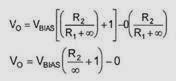
From the above equation we see that the output voltage is equal to the polarization voltage (VBias). Therefore, the voltage at both inputs and the voltage output of the operational amplifier are equal. Due to the presence of the input capacitor, the voltage gain of the amplifier AC now depends on the frequency of the signal applied to the input of the amplifier. The capacitor CIN input and resistor R1 form a high pass RC filter. The values R1 and CIN determine the low cut-off frequency of the amplifier. The frequency at which the voltage gain is decreased by -3dB, is the low cut-off frequency, and can be determined using the following equation:

For example, if CIN = 1pF and R1 = 10Kohm, then the low frequency cutoff is 15.9Hz. Signals having lower frequency than the cutoff frequency, are reduced by 20 decibels (20 decibels per decade) for each tenfold reduction in frequency (one decade corresponds to a ten-fold increase or decrease in frequency). If a capacitor is connected in series with the output, the capacitor will prevent the DC current and will only allow the AC signal to pass, and thus the bias voltage to the load by changing the voltage VBias of the earth (0 volts). The capacitor output together with the load RL forms a low pass RC filter which causes attenuation at low frequencies. Note that although the circuit shown in Figure 16 uses the smallest number of components, may be unsuitable in certain applications where the signal source, the load, and the proper input of the operational amplifier, it must be connected to a bias voltage in such cases should use the circuit shown in Figure 18. Notice that the voltage gain in the circuit shown in Figure 18 depends on agreements frequencies, due to the presence of the input capacitor. You may think that the circuit shown in Figure 18 will work correctly if removing the input capacitor CIN (Fig. 19), but, this capacitor must remain otherwise the circuit will not work correctly. The output voltage of the amplifier in Figure 19 is given by the following equation:

The above equation can be proved very simply by using the principle of ultra-rustling, as follows: First we set VBias = 0, the amplifier is now essentially an inverse amplifier and the output voltage is given by the following equation:
V0 = V0(-) + V0(+), or Observe that The above equation is the same as Equation 2 if you replace Z1 with R1.

In the absence of an input signal, the dc voltage at the output will try to become equal with

For example, if R1 = R2 = 10Kohm, Vcc = 10V, and VBias = 5V, then:
However, this is not possible because the maximum positive output voltage can have with this amp is less than +10 V.
Therefore, the output voltage is always less than the positive voltage of the power supply. Therefore, when an input signal applied alternating current, the output remains saturated during the negative half-period of the input signal. The output will also remain saturated just below the positive trend of +10 V of power supply, for the positive input signals. The circuit shown in Figure 20 is a correct AC amplifier that operates with a single power supply. The voltage between the reverse and correct input is substantially equal to zero volts. After VN = VD + VP and VD = 0, the input terminal of the reverse is also VBias = Vcc/2, relative to the earth. Therefore, both inputs of the operational amplifier is at the same voltage (VBias). The output voltage can be determined as follows:
The current I1 flowing through Z1 is equal to the current I2 flowing through resistor R2. The voltage across Z1 is equal to VB-VA, where VB = VBias and VA = 0.
So we have:

The voltage across R2 is equal to:
Vo = VB: therefore

Since I1 = I2, we have:

Again rearranging the above equation we take:

By multiplying both sides with R2 we get:

The impedance Z1 is given by the equation:

At DC (f = 0Hz), the resistance of the capacitor Cin is infinite:


We will now examine the various circuits to generate the dc voltage bias, which is sometimes called virtual ground. Before you choose a circuit output dc voltage bias must specify load regulation, power supply rejection, power dissipation and the output impedance of the circuit bias. The final decision on what bias circuit will be used in an application depends on the cost and the space we have available to us. The simple voltage divider shown in Figure 21, can be used to produce the constant bias voltage (VBias). This circuit has low load regulation. I.e. as the load current increases, the output voltage of this circuit (bias voltage) is reduced. An explanation of the load regulation and line regulation given below.


Figure 22(a). Equivalent circuit of an ideal power supply, (b) Equivalent circuit of an actual power supply.
An ideal power supply provides an output voltage that remains constant regardless of the load current, and is also independent of temperature variations, and also from any changes in the supply voltage of the alternating current network. Figure 22A shows the equivalent circuit of an ideal power supply. In the case of a practical power supply, the output voltage decreases as the load current increases. This is why a real power has an equivalent internal resistance, because of the various components of which consists of the power supply circuit. The equivalent circuit of an actual power supply shown in Figure 22b, where VNL is the output voltage with an open circuit (ie the output voltage when there is no load at the output terminals of the power supply), and R1 is the total internal resistance of the power supply. When a load is connected to the output of the power supply, the output voltage, ie the voltage across the load (VL = IL x RL) is less than the output voltage (VNL) with open circuit. This is because the resistors RL, and RI, form a voltage divider and the voltage across the load is given by:

When the load current increases, the voltage drop across the internal resistance RI also increases, and therefore, the output voltage decreases. The reduction of the output voltage as the load current increases, is a disadvantage. The output voltage of a typical power supply compared to the load current is shown in Figure 23. An ideal power supply has an output voltage that is constant regardless of the load that connects to the output terminals. Obviously, if the internal resistance RI is zero or very small compared to the RL, then output voltage VO is constant and equal to the VNL. The change of the DC output voltage of the power supply relative to the continuous load current is called, simply load regulation or regulation.
The regulation is defined as follows:

The load regulation can be expressed as a percentage:

An ideal power supply would have 0 load regulation, since an ideal power supply is:
Example. The open circuit voltage (i.e., when RL = infinity) of a power supply is VNL = 20V, and when a load is connected to terminals of the power supply, the output voltage drops to 15V. The load regulation of the power supply is given by:


Ie the regulation of the power supply is 25%.
Tuesday, October 28, 2014
LM12 High Power Amplifier circuit
 This is an amplifier circuit using ic LM12 as the main amplifier. This amplifier has a 150Watt power output and has a 4 ohm impedance. These amplifiers have a classified high output power. The frequency response of 10Hz to 30KHz. Supply Voltage at least 9 Volt and 50 Volt CT.
|
| Schematic High Power amplifier with LM12 |
Monday, October 27, 2014
45W Power Amplifier include Tone Control
 |
| 45W Power Amplifier include Tone Control |
Switch Mode Power Supply
 |
| Switch Mode Power Supply Circuit |
Thursday, October 23, 2014
Power Amplifier for Audio Laptop

Adapter power supply and charger circuit
 |
| Adapter, power supply and charger circuit |
Saturday, October 18, 2014
CA3140 TIP41 2N3055 Lab Power Supply 0 30V 2A

This is the schematic of the 30V/2A power supply I use in my own lab.It may look very complex, but it really isn’t very difficult to understand: it uses only the knowledge we’ve learned in the previous lessons.
The top part looks like the power supply we built in Lesson 7: the transformer L1 transforms the outlet voltage to a safe 30V, which is rectified by bridge rectifier G2 and smoothed by capacitor C5. Transistors T3 and T6 form a darlington transistor. This darlington replaces transistor T1 in Lesson 7. However, the base voltage is not controlled by a simple potmeter, but by an ‘electronic potmeter’ with voltage feedback. The advantage of this feedback is a load-independent output voltage.
Read more original source:
http://www.hobby-electronics.info/go.php?to=11000
Monday, October 13, 2014
13 8V 40A High current Power Supply

My good Friend want circuit power supply for VR (Radio Sound), I find to this good Website.
more 13.8V power supply
Intro Detail :

SPECIFICATION
· Input voltage: 240
· Output voltage: 13.2V DC
· Output current: 40A DC
· Over current protection: current limiting al 40A
· Short circuit protection: Regulator shut off.
· Over voltage protection: Shuts off DC input and discharges input stage reservoir.
· Over temperature protection: Fan automatically operates as heat sink temperature of 65°C.
· Indicators: Power ON LED and Short circuit Protection active LED.
THIS PROJECT describes a Protected 13.2V 40A Power Supply Unit which, provided the heat sinking and cooling fan are suitable, is capable of running at full power at 100% duty cycle. It features soft starting, over voltage, current limiting, short circuit protection and automatic fan control. It is a substantial project that is not for the novice constructor.
CIRCUIT DESCRIPTION
THE HEAVY CURRENT carrying connections are shown in bold in Fig 1. The mains input passes through an EMC filter, protection fuse F1 and ON/OFF switch S 1 to transformer TI. The secondary output of TI is rectified by D I but cannot pass through open relay contacts RL1a. To start the PSU switch, S2 is operated allowing limited current to pass via R1 to slowly charge the reservoir capacitor C1. As C1 charges, the RL1 a pulls in closing the relay contacts and shorting out R1 and S2 placing the PSU in the ON state.
Voltage regulator IC1 is the popular 723. A 7.2V reference on IC 1:6 is fed to non-inverting ICI:5. This is compared with a sample of the PSU output voltage via RI3, RI4 and R15 to inverting input at ICI:4. The 723 can source 150mA at ICl:10, so transistor TR2 acts as a Darlington driver for the pass transistors TR3 to TR7 inclusive. Resistors R21 to R25 are current sharing resistors and the voltage across them is proportional to the current drawn by the PSU load.
When the current through R21reaches 8A (i.e. a total PSU current output of 40A) the voltage across R11 and R12 is 0.88V and is tapped from R I I to bias a transistor inside IC1 which robs IC1: 10 of some current, forcing the PSU into a current limiting mode.
