Showing posts with label car. Show all posts

Thursday, December 11, 2014

Car Laptop Power Supply Adaptor
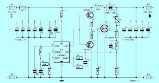
laptop-adaptor-schematic
The laptop adaptor described here plugs into a car cigarette lighter socket and produces a 19V nominal output voltage adjustable by + - 0.5V. The input voltage range is from 9.2V to 15V and the output voltage shows good regulation even with large fluctuations of the input voltage. 
Read More..

Monday, November 17, 2014

Radio Control for toy car

play toy cars controlled by radio signals is an interesting game. The much-loved toy cars children, plus a simple circuit would be ideal for toy cars. This series of families use traditional digital CMOS IC which requires a very small electric current, so it does not impose on the performance of the original toy cars.
In this system, radio signals emitted not continuously but only generated when the controller sends a command left / right or forward / backward, and even then only a radio frequency of an intermittent, so it is sending pulses of radio wave frequency.

Number of pulses sent represents a command is sent, the command GO is represented by 8 pulses, represented by 16 pulses LEFT, RIGHT DOWN 32 pulses and 64 pulses. Command sent to a combination of two orders once gus, which is a combination of command forward / backward and right / left, for example, could be sent forward command and left once gus, in this case the number of pulses sent is 24, which is the sum of the forward command command as much as 8 pulses and left as many as 16 pulses.
Once a command is sent, the system stops sending commands in a certain time lag, the lag time it takes the receiver circuit will have sufficient time to execute properly. Frequency pulses were visible on the right side of Figure 1.

How it works The transmitter
Radio signals generated by the oscillator circuit formed by transistors Q1 9016, the working frequency of the oscillator is determined by the crystal Y1 is worth 27.145 MHz. A very critical part of this oscillator circuit is T1, L1 and L2, which specifically dealt with separately at the end of this article.
Work of the oscillator is controlled by a NOR gate U2D 14001, while the output gate (pin 3) is worth 1 , the oscillator will work and transmit radio frequency 27.145 MHz, and at the output U2D value 0 the oscillator will stop working.
U2D NOR gate receives the clock signal from the NOR gates U2B. NOR gate CMOS type with the help of resistors R4 and R5 and capacitor C8 to form a low frequency oscillator circuit to control the clock shaper of existing digital circuits. Working from the clock generator is controlled via the input leg 6, the circuit will generate the input clock that is berlevel 0 .
NOR gate U2A and U2C form a latch circuit (RS Flip Flop), due to the influence of resistor R2 and capacitor C11 which is fed to pin 9 on U2C, when the circuit gets power supply output U2C must be 1 and U2A output (pin 3) to 0 . This situation resulted EUIS clock generator generating a clock U2B work and release the reset state of the enumerator 14 024 IC (U1), so that the U1 start chopping and 27.145 MHz oscillator circuit to send pulses of the clock generator frequency during work.
At the start chopping, all the output IC 14 024 enumerators in kedaan 0 , after chopping the 8 pulse output Q4 (pin 6) will be 1, after chopping 16 Q5 pulse output (pin 5) to 1 , after chopping 32 Q6 output pulse (pin 4) to 1 , after 64 counts pulses output Q7 (pin 3) to 1.
Outputs are used to control the voltage above 9 feet U2C through diode D1 and D2, as long as it remains one of the output value 0 then the plant U2B clock still works, it will continue until dankatode D2 D1 cathode to 1 so that the foot 9 U2C a 1 as well. This situation will lead to 3 feet U2A output to 1 , which stops the clock generator and reset U2B enumerator 14 024 danberhenti is sending pulses of frequency 27 145 MHz.
To generate the lag time for the receiver circuits have enough time to perform the command, used a series of 9014 Q2, the resistor R7 and capacitor C10. The magnitude of the delay time is determined by the value of R7 and C10. The switch to send the command forward / backward and to send the command left / right are two separate switches. Each switch has three positions, the center position means that the scalar does not send commands.
How It Works Recipients
Figure 2 is a recipient of a series of paired images dimobil toy, serves to receive signals from the transmitter to control the motor cars, so cars can move forward / backward and left / right. Transistor Q1 with the help of resistors; capacitors and T1 form as a series of 27.145 MHz radio signal receiver. T1 in series with a T1 is exactly the same used in the transmitter circuit, how to make it are discussed below.
Transistor Q2 perlangkapannya formed following a series of pulses to change the radio frequency received from the transmitter into the box pulses that can be accepted as a digital signal by the CMOS IC. Digital signal will be received as the clock had to be chopped by enumerator 14 024 IC (U2). Output of 14 024 would correspond to the number of pulses sent by the transmitter, forward command and left (which is used as an example in the discussion of the transmitter) is the pulse number of 24, the enumeration of these pulses resulted in 14 024 to be output Q4 = 1 , Q5 = 1, Q6 = 0 and Q7 = 0.
The received digital signal other than U2 used as counter clock IC 14 024 discussed above, is also used to move the 3 pieces of the time delay circuit to generate pulses which controls the sequence of work.
The first control pulse will appear after submission frequency pulse stopped because the lag time between sending the code, this pulse count function to record the results of 14 024 to 14 042 U3 (D Flip Flop), so that the final condition of 14 024 will be retained to control the motor. After the results were recorded for 14 024 14 042, 14 042 counter is reset by the second pulse, so that after the lag time counter counts up starting from 14 042 to 0 again.
Circuit formed by transistors Q3, Q4, Q7, Q8, Q9 and Q10 H Bridge is named as a series, this series is very powerful to drive the DC motor. With this circuit the DC motor can be rotated to the right-to-left or stop motion. The main requirement is the use of this circuit Q7 and the base voltage of Q10 base voltage must be opposed, for example, the base Q7 = 1 and the base of Q10 = 0 motor rotates to the left, the base of Q7 = 0 and the base of Q10 = 1 motor will turning to the right, the base Q7 = 0 and Q10 base = 0 motor stop motion, but should not be happening base Q7 = 1 and the base Q10 = 1.
Similarly, Q5, Q6, Q11, Q12, Q13 and Q14 form an H Bridge. H Bridge to the left in Figure 2 is used to control a motor that regulates the movement of cars left / right, while the H Bridge to the right is used to control a motor that regulates the movement forward / backward cars.
The relationship between outpur enumerator 14 042 and input D Flip Flop 14 024 is arranged such that the signal is fed to each of the H Bridge can not be all 1 simultaneously.


Manufacture of transformer TX and RX
Transformer T1 in the series transmitter and receiver, is the same stuff, and have made ​​themselves. Transformer was built using a plastic transformer Koker (spare part radio) that has a step that appears 5 lines that can be filled with coils of wire, as shown in the photograph. Wearing this Koker facilitate wire transformer windings. Otherwise it could be similar Koker, just the usual wear. Koker is a small transformer and feritnya also small (3 mm) as that used to be used for the assembly of CB 27 MHz radio.
Can wear a wire to wire the transformer in the unloading of Koker, carefully open coil of wire that already exist in the Koker because the wire is quite smooth and quite easy to break.
Step 1: rolls of wire which is numbered 5 feet to 4 feet in the direction of h (CW) for 3 rolls right on level 1 (pathway level above the bottom line)
Step 2: Roll the wire from 1 foot to 2 feet in a clockwise direction as much as 4 rolls right on level 2.
Step 3: Continue the roll (from step 2) in a clockwise direction as much as three quarter roll to 3 feet on three levels. (Can be determined exactly a quarter of the roll, because it has a track kokernya split into 4).
Manufacture of coil L1
Roll of copper wire diameter from 0.3 to 0.5 mm by 10 quarter rolls on Koker diameter of about 4 mm (which will be released) is also in a clockwise direction.
Manufacture of coil L2
Roll of copper wire 0.1 mm diameter by 50 rolls in plastic Koker without ferrite diameter of about 3.5 - 4 mm (look for the plastic material from scrap) is also in a clockwise direction. Long section on liputi rolls along the 5 mm.
Read More..

Wednesday, November 5, 2014

Car Bulb Power Flasher

Derived from the Two-wire Lamp Flasher design, hosted on RED Free Circuit Designs since 1999, this astonishingly simple circuit allows one or two powerful 12V 21W car bulbs to be driven in flashing mode by means of a power MosFet. 
 
Devices of this kind are particularly suited for road, traffic and yard alerts and in all cases where mains supply is not available but a powerful flashing light is yet necessary.

Car Bulb Power Flasher Circuit Diagram:

Flash

Car Bulb Power Flasher  Parts List:

Parts Description
R1 6.8K
R2 220K
R3 22K
C1 100uF-25V
C2 10u-25V
D1 1N4002
Q1 BC557
Q2 IRF530
LP1 12V-21W Car Filament Bulb (See Notes)
SW1 SPST Switch (3 Amp minimum)
Notes:
  • Flashing frequency can be varied within a limited range by changing C1 value.
  • As high dc currents are involved, please use suitably sized cables for battery and bulb(s) connections.

Read More..

Tuesday, October 28, 2014

2 Channel MOSFET Car Audio Amplifier

BossThis Car Audio Amplifier to run an older 8 inch pioneer sub in a bandpass box . This delivers as expected. Subwoofer sounds perfect. I tried to run it off the stock deck using the high pass but it wouldnt turn on. I took a jumper wire and touched the remote to the positive and it fired up immediately. Dont expect any help from Boss via their phone number on the box. I waited for 20 minutes before I just decided to hang up and just pick up a new deck. It sounds great.

That this amp would not do a good job pushing a subwoofer is that it only has a "Subwoofer level control". This is not to be mistaken for a crossover/low pass filter. You need some form of crossover to keep it from sending high frequencies to the speaker.

Technical Detail for Boss Audio R1002 2-Channel Mosfet Power Amplifier with Remote Subwoofer Level Control :

  • 2-Channel MOSFET Power Amplifier
  • Remote Subwoofer Level Control Included
  • 100W x 2 Max Power
  • 100W x 2 RMS Power
  • 50W x 2 Max Bridged Power
Read More..

Sunday, September 21, 2014

All about Kenwood car audio

Kenwood products have repeatedly set the benchmark for performance, innovation and reliability for years.

Kenwood products have repeatedly set the benchmark for performance, innovation and reliability for years. Kenwood strives to produce products that will not be obsolete in the near future as well as products that the consumer will be proud to own. Kenwood is also always looking toward the future and keeping its products up-to-date with the latest technology without the consumer having to worry about their entertainment gear being up-to-date. This concept is what Kenwood calls ‘Future Ready/Already’.

Kenwood has always been Future Ready/Already even in the beginnings of the Kenwood Company. The Kenwood Company began by designing and manufacturing Japan’s first FM tuner and solid-state amplifier. After the FM tuner, the company built the most popular stereo receiver ever to sell in the United States. In 1981, Kenwood invented the world’s first audio/video amplifier and audio/video system, many years before other companies would come out with home theater products like them. Kenwood kept the invention streak rolling with the introduction of the first anti-theft car stereo in 1984. All these milestones in Kenwood’s history prove that they are Future Ready/Already.

20 years later, Kenwood is still proving that they are Future Ready/Already by introducing more products, such as the KTC-HR100 HD Radio™ tuner that is the first on the market or the Networked Home Theater Systems that play video and audio files from the home computer. Kenwood also has introduced the 3D MASK Pro™ 3-dimensional control and display system, A.M.S. ™ which is an amplifier management system, Typhoon woofer cones, K-STAT™ self-adjusting power transistors, and Image Enhancer™ tweeter technology. The 2004 Kenwood products bring entertainment of the future for the consumer to enjoy it today.

Staying Future Ready/Already keeps Kenwood examining and refining its products to keep ahead of the competition while pleasing the consumer that has come to depend on Kenwood. All emerging technologies are examined to determine how they can serve the entertainment needs of the consumer. Kenwood diligently searches for more improved ways to make them user friendly, accessible and invisible to the point where the consumer will not even think about the technology itself, the consumer will only know that they are enjoying the product. However, at

Kenwood, Future Ready/Already is more than just features and technologies. Kenwood believes that the future is now and when a consumer owns a Kenwood product, they are ready for tomorrow.

Kenwood offers the best sound and visuals available for the consumer to take on the road either across town or across the nation. The consumer can transform their vehicle into a movie theater, drown out the sound from competition, improve their navigation around town or just simply enjoy the music they enjoy. In addition, with Kenwood’s idea that the future is now, the entertainment gear offered by them is always future ready.

With all the focus that Kenwood puts on their products, they are always ready for yesterday, today and more importantly tomorrow. Kenwood strives to keep there consumers up-to-date which in turn makes for consumers who will become brand loyal to Kenwood.
Read More..

Tuesday, September 16, 2014

Simple Low Power Car Stereo Amplifier

A simple low power car stereo amplifier circuit based on TDA 2003 is shown here. The circuit uses cheap, readily available components and it is very easy to construct. TDA2003 is an integrated car radio amplifier from ST Micro electronics that has a lot of good features like short circuit protection for all pins, thermal over range low harmonic distortion, low cross over distortion etc. 

Circuit diagram :

 A simple low power car stereo amplifier Circuit Diagram


In the circuit given here each TDA2003 is wired as a mono amplifier operating from a 12V supply. Resistors R2 and R3 forms a feedback network that sets the amplifiers gain. C7 is the input DC de-coupling capacitor and C5 couples the speaker to the amplifiers output. C4 is used for improving the ripple rejection while C1 and C2 are employed for power supply filtering. C3 and R1 are used for setting the upper frequency cut-off. Network comprising of C6 and R4 is used for frequency stabilization and to prevent oscillation.

Notes.

  • Assemble the circuit on a good quality PCB.
  • Heat sinks are necessary for both ICs.
  • The circuit can be operated from 12V DC.
  • S1 is the ON/OFF switch

Read More..

Monday, September 15, 2014

10W CAR RADIO AUDIO AMPLIFIER

DESCRIPTION:

The TDA 2003 hasimproved performancewith the same pin configuration as the TDA 2002. The additional features of TDA 2002, very low numberof externalcomponents,ease of assembly, space and cost saving, are maintained. Thedeviceprovidesa high outputcurrentcapability (up to 3.5A) very low harmonic and cross-over distortion. Completely safe operation is guaranteed due to protectionagainst DCand ACshort circuit between all pins and ground,thermal over-range,load dump voltage surge up to 40V and fortuitous open ground.

Circuit diagram:
Circuit diagram 10W CAR RADIO AUDIO AMPLIFIER


Read More..

Tuesday, September 2, 2014

TDA8566 2x40 W 2 Ω stereo BTL car radio power amplifier

Description of TDA8566:

The TDA8566 is an integrated class-B output amplifier which is available in several packages. TDA8566TH is contained in a 20-lead small outline plastic package. The  TDA8566TH1 is a 24-lead small outline plastic package which is pin compatible with the 2C-bus controlled amplifier TDA1566TH for one board layout. TDA8566Q is a 17-pin DIL-bent-SIL package. The device contains 2 amplifiers in a Bridge-Tied Load (BTL) configuration. The output power is 2 × 25 W in a 4 Ω load or 2 × 40 W in a 2 Ω load. It has a differential input stage and 2 diagnostic outputs. The device is primarily developed for car radio applications.

Features TDA8566:
  • Differential inputs
  • Very high Common Mode Rejection Ratio (CMRR)
  • High common mode input signal handling
  • Requires very few external components
  • High output power
  • 4 Ω and 2 Ω load driving capability
  • Low offset voltage at output
  • Fixed gain
  • Diagnostic facility (distortion, short-circuit and temperature pre-warning)
  • Good ripple rejection
  • Mode select switch (operating, mute and standby)
  • Load dump protection
  • Short-circuit proof to ground, to VP and across the load
  • Low power dissipation in any short-circuit condition
  • Thermally protected
  • Reverse polarity safe
  • Protected against electrostatic discharge
  • No switch-on/switch-off plops
  • Low thermal resistance
  • TDA8566TH1 is pin compatible with TDA1566TH

Applications:
  • Home-sound sets 
  • Multimedia systems 
  • Car audio (boosters)
Circuit diagram TDA8566:

TDA8566 2 × 40 W/2 Ω stereo BTL car radio power amplifier with differential inputs and diagnostic outputs

Datasheet for TDA8566: Download
Where you can buy: Aliexpress
Where you can buy: DealExtreme
Read More..

Sunday, August 31, 2014

4 x 6 5W QUAD POWER AMPLIFIER FOR CAR RADIO

Features:

MINIMUM EXTERNAL COMPONENT COUNT
HIGH CURRENT CAPABILITY
NO BOOTSTRAP CAPACITORS
NO BOUCHEROT CELLS
CLIP DETECTOR OUTPUT
HIGH OUTPUT POWER
HIGH APPLICATION FLEXIBILITY
FIXED GAIN
VERY LOW STAND-BY CURRENT (1µA typ)
NO SWITCH ON/OFF NOISE

Application circuit:
Circuit Diagram for TDA7370
PCB LAYOUT TDA7370
pcb layout

Read More..

Saturday, August 16, 2014

4 x 44 W into 4 Ω or 4 x 75 W into 2 Ω quad BTL car radio power amplifier

General Description

The TDA8591J is a quad BTL audio power amplifier comprising four independent amplifiers in Bridge Tied Load (BTL) configuration. Each amplifier has a gain of 26 dB and supplies an output power of 75 W (EIAJ) into a 2 Ω load. The TDA8591J has low quiescent current and is

primarily developed for car audio applications.

Circuit Diargram
4 x 44 W into 4 Ω or 4 x 75 W into 2 Ω quad BTL car radio power amplifier


Read More..

Friday, August 15, 2014

Musical car reverse horn circuit

Here is a simple schema that will produce a musical horn when ever your car is in reverse gear.The schema uses two ICs for the operation ,voltage regulator 7805(IC1) and musical tone generator UM66(IC2).The IC1 reduces the car battery voltage to 5V.The diodes D1 & D2 in combination produces an additional drop of 1.4 V to give a 3.6 V supply for the UM66.The supply voltage of UM 66 should not be more than 4V.When ever the car is in reverse gear ,the reverse gear switch of the car gets activated and the schema gets connected to the car battery.The UM66 starts playing the music tone.The transistor T1 amplifies the output of UM66 to drive the loudspeaker.


Notes.

* Assemble the schema on a good quality PCB or common board.
* Place the schema on a waterproof place in the dashboard.
* The switch S1 is the reverse gear switch of the car.
* Before attempting the schema,have a good idea about the electrical wiring of your car.A wrong connection may damage your car’s electricals.
* The transistor Q1 is not very specific.Any medium power NPN audio transistor will do the job.You could easily find one from your electronics junk box.


Read More..