Showing posts with label volt. Show all posts

Tuesday, November 18, 2014

POWER SUPPLAY 13 8 Volt Schematic

POWER
POWER
POWER
POWER

Part list for 12 Amp BDX33-based power supply:

  • 2 x 15 volt 6+ amps

  • 2 times two MR750 (MR7510) diodes (MR750 = 6 Ampere diode) or 2 times 3 1N5401 (1N5408) diodes.

  • F1 = 1 Amp

  • F2 = 15 amp

  • R1 2k2 1 Watt

  • R2 10k

  • R3 1k 0.5 watt

  • R4,R5,R6,R7 0.1 ohm 10 watt

  • R8 4.7

  • R9 6k8

  • C1 two times 4700uF/35v

  • C2 330uF/35v

  • C0,C3,C4,C6,C10 100nF

  • C7 330uF/25v

  • C8 47nF

  • C9 47uF/25v

  • D1 1N5401

  • D2 LED

  • D3, D4, D5 1N4001

  • IC1 78L15

  • relay 12 volt 2x5 amp switching

  • 3 darlington transistors: T0,T1,T2 = BDX-33 NPN TO-220 transistor

  • Zd 8 or 9 volt, 5 watt

  • P1 2k trimmer

If using a bridge rectifier (like in schematic 2) you do not need 2 x 15 volts 6 amps, but 1 x 15 volt 10+ Amps

Part list for 20 Amp BDX33-based power supply:

  • 2 x 15 volt 12+ amps

  • 2 times 3 MR750 (MR7510) diodes (MR750 = 6 Ampere diode) or 2 times 5 1N5401 (1N5408) diodes.

  • F1 = 2 Amp

  • F2 = 25 amp

  • R1 2k2 1 Watt

  • R2 10k

  • R3 1k 0.5 watt

  • R4,R5,R6,R7 0.1 ohm 10 watt

  • R8 4.7

  • R9 6k8

  • C1 22000uF/35v

  • C2 330uF/35v

  • C0,C3,C4,C6,C10 100nF

  • C7 330uF/25v

  • C8 47nF

  • C9 47uF/25v

  • D1 1N5401

  • D2 LED

  • D3, D4, D5 1N4001

  • IC1 7815

  • relay 12 volt 10 amp switching

  • Four darlington transistors: T0,T1,T2,T3 = BDX-33 NPN TO-220 transistor

  • Zd 8 or 9 volt, 5 watt

  • P1 2k trimmer

If using a bridge rectifier (like in schematic 2) you do not need 2 x 15 volts 12 amps, but 1 x 15 volt 20 Amps

Read More..

Sunday, November 16, 2014

Digital Volt Meter Circuit

Digital volt meter circuit is simple and not much use of additional components. Volt meter circuit uses IC L7107 as a main actor. L7107 IC is an Analog to Digital Converter (ADC) which has been equipped with the viewer seven segment driver 3 1 / 2 digits. IC L7107 in the application of digital volt meter is in it has been equipped with an internal voltage reference circuit, analog switches, sequential control logic, and LED display driver. This digital meter volt circuit can be operated with a working voltage 5VDC. A full suite of digital volt meter can be seen in the following figure.

Digital

To set or Calibration to 0 Volt. done by adjusting the VR 2KOhm. then to test the display can be done by pressing the test switch, where to normal conditions when the switch is pressed then all the display lights up.
Read More..

Friday, November 7, 2014

9 Volt Power Supply Circuit Diagram Using IC 7809

Description
Circuit showing a 9 volt power supply . Here we have used a bridge rectifier and 7809 ic for making this circuit.Where the ic regulate the output to 9 v,1 A .This voltage every time constant.Are you interested ?

Circuit diagram with Parts list.  


Notes. 
  • If a current of 300 mA or above is required, fit a proper heat sink to the IC 7809.
  • If 1A bridge is not available, make one using four 1N 4007 diodes.
Read More..

Monday, September 15, 2014

12 Volt 30 Amp PSU Wiring diagram Schematic

Using a single 7812 IC voltage regulator and multiple outboard pass transistors, this power supply can deliver output load currents of up to 30 amps. The design is shown below:

Simple 12 Volt 30 Amp PSU Circuit Diagram

Simple

Notes:
The input transformer is likely to be the most expensive part of the entire project. As an alternative, a couple of 12 Volt car batteries could be used. The input voltage to the regulator must be at least several volts higher than the output voltage (12V) so that the regulator can maintain its output. If a transformer is used, then the rectifier diodes must be capable of passing a very high peak forward current, typically 100amps or more. The 7812 IC will only pass 1 amp or less of the output current, the remainder being supplied by the outboard pass transistors. As the schema is designed to handle loads of up to 30 amps, then six TIP2955 are wired in parallel to meet this demand. 

The dissipation in each power transistor is one sixth of the total load, but adequate heat sinking is still required. Maximum load current will generate maximum dissipation, so a very large heat sink is required. In considering a heat sink, it may be a good idea to look for either a fan or water cooled heat sink. In the event that the power transistors should fail, then the regulator would have to supply full load current and would fail with catastrophic results. A 1 amp fuse in the regulators output prevents a safeguard. The 400mohm load is for test purposes only and should not be included in the final schema. A simulated performance is shown below:

 12 Volt 30 Amp PSU Circuit Diagram

Simple


Calculations:
This schema is a fine example of Kirchoffs current and voltage laws. To summarise, the sum of the currents entering a junction, must equal the current leaving the junction, and the voltages around a loop must equal zero. For example, in the diagram above, the input voltage is 24 volts. 4 volts is dropped across R7 and 20 volts across the regulator input, 24 -4 -20 =0. At the output :- the total load current is 30 amps, the regulator supplies 0.866 A and the 6 transistors 4.855 Amp each , 30 = 6 * 4.855 + 0.866. Each power transistor contributes around 4.86 A to the load. The base current is about 138 mA per transistor. A DC current gain of 35 at a collector current of 6 amp is required. 

This is well within the limits of the TIP2955. Resistors R1 to R6 are included for stability and prevent current swamping as the manufacturing tolerances of dc current gain will be different for each transistor. Resistor R7 is 100 ohms and develops 4 Volts with maximun load. Power dissipation is hence (4^2)/200 or about 160 mW. I recommend using a 0.5 Watt resistor for R7. The input current to the regulator is fed via the emitter resistor and base emitter junctions of the power transistors. Once again using Kirchoffs current laws, the 871 mA regulator input current is derived from the base chain and the 40.3 mA flowing through the 100 Ohm resistor. 871.18 = 40.3 + 830. 88. The current from the regulator itself cannot be greater than the input current. As can be seen the regulator only draws about 5 mA and should run cold.
Read More..

Saturday, August 30, 2014

6N2P Tube Pre Tone Low Volt Low Cost Wiring diagram Schematic

6N2P Tube Pre-Tone Low Volt & Low Cost Circuit Diagram, I would like to present the low voltage and low cost for beginner developer. This is the kind 6n2p Triode Vacuum Tube Russia Tube very cheap compared to other tube models. Only cost $ 10-15 for a true beginner. Also easy to find in the market .

The quality of their own personal thoughts of my own. Well honestly say that sometimes can get resistant. Instead of a 12AX7 plugged it by changing the pressure tube, topped only cycle . I try to create this Use only one tube. Working as a stereo (two halves of a single lamp), using low power as well.

  6N2P Tube Pre-Tone Low Volt & Low Cost Circuit Diagram
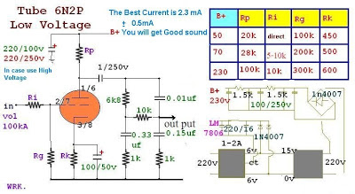
 6n2p tube pre-tone low volt & low cost circuit diagram


That if one wants to create a high fire. Put values ​​as I get it offline because I reference values ​​from the Data Sheet.

But do not suggest we fire up to 250 Volts Capacitor find the 350v. The price is expensive and over again.
I recommend creating a 230v. And then use the Cap 250 v. easy to find cheap used instead of the sound was no difference between voltage 250 to 230.

 6n2p tube pre-tone low volt & low cost circuit diagram

The trial was a pre-tone light bulb with + – 35 Volts with the famous schema 741. But output is not satisfactory offline … hum a lot. Experimental values ​​are being changed. To complete the schema. Before, and I will be published offline because many people complained that the transformer is quite difficult to find ideas to this schema.

I do, then listen to the sound does not make sense at first, it offline. Central held very outstanding voice .. much agitation. But keep it open for a few days … to draw a lot more sense … mixing different sounds much less. Really listen. Voice is getting better offline …. now I’m comparing 12AX7. 6DJ8 6N2P 6N23P them on . wait a minute per well offline. Pictures show that I was to hear of the TDA2030 OTL 30watt.
Read More..

Tuesday, August 12, 2014

1 5 volt dual LED flasher Wiring diagram Schematic

This 1.5 volt led fasher runs more than a year on a single d" cell and alternately flashes 2 LEDs at about a 1 second rate. The schema employs a 74HC14 CMOS hex inverter that will operate at very low voltages (less than 1 volt). One section is used as a squarewave oscillator (pins 1 and 2), while the others are wired to produce a short 10mS pulse on alternate edges of the square wave so the LEDs will alternate back and forth. The output sections each use a capacitor charge pump to increase the voltage for the LEDs. 

The schema draws an average current of 800uA from the D battery and the LED peak current is about 40mA with a fresh battery and drops to about 10mA as the battery voltage falls to 1.1 volts. The capacity of a alkaline D cell is about 12 amp hours with a cutoff voltage of 1.1 so the schema should run about 12/.0008 = 15000 hours or maybe 625 days, but I havent verified that yet. The idea for this schema came from a single 1.5 volt LED flasher by Dave Johnson that can viewed at

1.5 volt dual LED flasher Circuit Diagram


1.5 volt dual LED flasher Circuit Diagram


Author : Bill Bowden 
Read More..