Thursday, November 20, 2014
1 Lamp with 2 switches
Series 1 light 2 switch configuration is intended to control lights from two locations arefar apart. Application of series 1 light with 2 switches are often implemented in thehallway or tunnel. In the application in a hallway or tunnel, with a series like this we can turn on or turn off the light from each tunnel or hallway door. The number of lights can bereproduced by paralleling. The circuit is very simple because only built of 1 and 2pieces of fruit lamp selector switch. If you want to use a lamp with a power greater then the switch can be replaced with 1 piece contactor (relay) for each switch. Then switchused to turn on and turn off the relay replacement S1 and S2.

The working principle with 2 series 1 light switch is the light will light when the S1 and S2 different position, and the lights will be on at the time of the switch position S1 and S2 together. In the installation of switches S1 and S2 each put at the end of the hallway or tunnel.

Mini Amplifier with 3 Transistor
Mini 3 transistor amplifier is a simple amplifier with 50mW power drawn by 3 transitor.
The series of three mini-amplifier transistors can be used for loud speaker 8 ohm load. Source voltage required to activate the mini-amplifier can be drawn from the batteries 9V.Rangkaian 3 transistor amplifier is often used in simple portabe audio devices such as radios or small tape recorder. Mini-transistor amplifier circuit 3 is quite simple as shown in the figure below.

Mini-transistor amplifier circuit 3 includes type of amplifier OTL (Output Transformer Less). Mini-transistor amplifier circuit 3 is used for output coupling capacitors. Amplifier circuit is simple and suitable when used for audio amplifier experiment.
Read More..
The series of three mini-amplifier transistors can be used for loud speaker 8 ohm load. Source voltage required to activate the mini-amplifier can be drawn from the batteries 9V.Rangkaian 3 transistor amplifier is often used in simple portabe audio devices such as radios or small tape recorder. Mini-transistor amplifier circuit 3 is quite simple as shown in the figure below.
Mini-transistor amplifier circuit 3 includes type of amplifier OTL (Output Transformer Less). Mini-transistor amplifier circuit 3 is used for output coupling capacitors. Amplifier circuit is simple and suitable when used for audio amplifier experiment.
Improving Performance Bass Amplifier
Stereo power amplifier is less in the bass tones, but if a speaker that sounds just feels solid bass sound, there are several possibilities, the first one speaker cable upside down, try alternating bass and tone tests.
If still, you need to use 2 power supply or attempting to use this circuit. Note this circuit works for a power amp that is less power transformer with 2 speakers (stereo). One of the speaker cable (output) should be reversed, this is okay, just a game to lighten the work phase transformer from the blow bass.
If still, you need to use 2 power supply or attempting to use this circuit. Note this circuit works for a power amp that is less power transformer with 2 speakers (stereo). One of the speaker cable (output) should be reversed, this is okay, just a game to lighten the work phase transformer from the blow bass.
We recommend that before you try this circuit, turn one speaker cable and a second test speakers with bass tones, the bass should be mutually reduce (bass-bass = 0). Next remove the driver from boknya and turn the speakers (the speaker drivers facing into the wall), the bass should grow (bass + bass = 2bass). One record store in the town of Indramayu is taking this simple way, certainly looks magnet speakers, great.
The heart of this circuit using IC with 2 op-amps, can type JRC4558, LF353, TL072, TL082, and similar. Vcc = + /-70Vdc. If Vcc = + /-42Vdc, replace the value of R9 and R10 to 2K2.
Op-amp 1 functions as a buffer, while the op-amp to-2 function as inverting the phase 180 , both have a reinforcement of 1 times.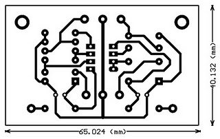

List of components:
R1, 2,5,6 .......... 100K
R3, 4 ................ 2K2
R7 ................... 100
R9, 10 .............. 2K2-3K3
C1, 2 ............... 100uf/25V
D1, 2 ............... 15V Zener
IC1 ................. TL072
Wednesday, November 19, 2014
TDA 7012T FM Radio Receiver
FM Radio Receiver IC TDA 7012T is very simple, but it has an FM radio receiver sensitivity and good selectivity. Single Chip FM Receifer cool name of IC TDA7012T 7012T TDA is to build an FM receiver requires a few additional components. Feature contained in FM receiver IC TDA 7012T is quite tempting to an FM receiver. Among features an FM receiver TDA 7012T is a low-voltage applications micro affability arrangement (MTS), Frequency Loked Loop (FLL) to 76 KHz range and selectivity of FM receiver with RC Filter. In an article by FM Radio Receiver IC TDA 7012T can be seen in the FM receiver circuit which can be made.
Image Series FM Radio Receiver with IC TDA 7012T

From the picture above components to make the FM Radio Receiver IC TDA 7012T as follows:
R1 = 8kΩ2
R2 = 10kΩ
R3 = 390Ω
C1, C3 = 10nF
C2, C6, C9, C16 = 100nF
C4 = 33pF
C5 = 25pF trimmer
C7, C10 = 1nF5
C8 = 820pF C11 = 1NF
C12 = 68pF
C13 = 220pF
C14 = 47μF 10V
C15 = 3nF3
L1 = 36nH
L2 = 1μH,
IC1 = TDA7021T
Hopefully useful and become an idea in the manufacture of Mini FM Receiver with IC TDA 7012T
Programming Learning MCS51
Learning Programming MCS51 becomes mandatory we learn if we want to use the MCS51. In the first part of this Learning Programming MCS51 we will learn together about the basic programming language MCS51 microcontroller. Where to program MCS51 outline there are 2 core parts of pemrogramanya language is "Words Work" and "Object". In the article Programming MCS51 this first part we will study first the "verb" is a command group Peng-copies of data, the command group arithmetic and logic command group.
Reference to DATA IN PROGRAMMING MCS51
Data can be in many different places, thus known a few ways to describe the data (in English often referred to as Addressing Mode), among others, as follows:
The mention of constant data (immediate addressing mode): MOV A, # $ 20. Constant data is data that was in the instructions. Examples of this instruction has the data meaning a constant $ 20 (as a constant data marked with #) on-copy it into the accumulator A. What needs to be properly addressed in this order is the number $ 20 is part of the instruction.
Reference to data directly (direct addressing mode), this method is used to refer to data residing in memory by calling the memory number where the data are: MOV A, $ 30. Examples of these instructions have the meaning of data in the memory number $ 30 in-copy it to the accumulators.
At first glance these same instructions to the instruction constant data above, the difference above instructions using the # which marks the $ 20 is a data constant, whereas in this instruction because there was no sign # then $ 30 is a number from memory.
The mention of indirect data (indirect addressing mode), this method is used to refer to data residing in memory, if memory data storage is changing its location so that the memory number is not called directly but in-titip her into another register : MOV A, @ R0.
In this instruction versatile R0 register is used to record the number of memory, so that this instruction has a memory meaning that the number recorded in the contents of R0-copy it into the accumulator A.
Sign @ is used to mark the memory number stored in R0.
Compare this with the instruction memory number directly mention above, in this instruction first memory numbers are stored in R0 and R0 appoint a role which memory is used, so that if the value of R0 change the designated memory will also be changed as well.
In this instruction registers R0 functioning multipurpose container for the address register (indirect address register), other than all-purpose registers R0 R1 can also be used as a container for the address register.
Reference to data in the register (register addressing mode): MOV A, R5. This instruction has the meaning of data in all-purpose register R5 is copy it into the accumulator A. This instruction makes all-purpose registers R0 to R7 as a place to store data that is very practical that it works very fast.
The data referred to in the discussion above all in the data memory (including all-purpose registers are also located in data memory). In writing the program, often required standard table that is stored along with the program. Tables of this kind is really a data residing in program memory!
For this purpose, MCS51 have any mention of data in memory means programs conducted by indirect (indirect addressing code mode): MOVC A, @ A + DPTR.
Notice in this MOV instruction is replaced with MOVC, the additional letter C is meant to distinguish that this instruction is used in the program memory. (MOV without the letter C means that the instruction used in the data memory).
Sign @ is used to mark A + DPTR is used to indicate the number of contents in-memory copy it to the accumulator A, in this case the value stored in the DPTR (Data Pointer Register - 2 bytes) plus the value stored in accumulators A (1 byte) is used to refer to the program memory numbers.
Verb in AT89Cx051
Overall AT89Cx051 have as many as 255 kinds of instruction, which was formed by combining the verb and objects. "The verb is the group discussed the following:
PENG GROUP-COPY-DATA AN MCS51
Basic code for this group are MOV, abbreviation of MOVE, which means to move, though more correct to say this command have meaning copying the data. This can be explained the following: after the instruction MOV A, R7 done, accumulators A and all-purpose register R7 contains the same data, originally stored in R7.
MOV command is distinguished according to the type of memory AT89Cx051. This command is on the memory data is written into MOV, for example:
MOV A, $ 20
MOV A, @ R1
MOV A, P1
MOV P3, A
To use the program memory, this command is written into MOVC, there are only 2 types of wear MOVC instructions, namely:
MOVC A, @ A + DPTR; DPTR as register indirect
MOVC A, @ A + PC, PC as the register indirect
In addition, there is also known MOVX command, the command that is used for external data memory (X singkatakan from External). This command is only available to the MCS51 family members who have an external data memory, for example AT89C51 and so forth, and certainly not known by the group that tidam AT89Cx051 have external data memory. There are only 6 kinds of wear MOVX instruction, these instructions are:
MOVX A, @ DPTR
MOVX A, @ R0
MOVX A, @ R1
MOVX @ DPTR, A
MOVX @ R0, A
MOVX @ R1, A
GROUP ARIMATIK (ADD, ADDC, SubB, DA, MUL and DIV)
ADD and ADDC command
The contents of accumulators A plus the number 1 byte, the sum will be collected back in the accumulator. In this operation Carry bit (C flag in the PSW - Program Status Word) serves as a reservoir overflow of the sum. If the sum of the abundance (a value greater than 255) will carry bit value 1 , if not Carry bit value 0. ADDC same with ADD, only in bits Carry ADDC value in the previous process involved summed together.
Numbers 1 byte is added to the accumulator, can be derived from a constant, from the all-purpose register, memory data from memory number is called directly or indirectly, as shown in the following example:
ADD A, R0; register versatile
ADD A, # $ 23; a constant
ADD A, @ R0; no memory indirect
ADD A, P1; no direct memory (port 1)
ORDERS IN PROGRAMMING SubB MCS51
The contents of Accumulator A less the number 1 byte follows with Carry bit value, the reduction will be accommodated again in the accumulators. Carry bits in this operation also serves as a reservoir overflow of the reduction. If the reduction is abundant (score less than 0) bits Carry would be worth 1 , if not Carry bit value 0.
SubB A, R0; A = A - R0 - C
SubB A, # $ 23; A = A - $ 23
SubB A, @ R1
SubB A, P0
DA command
DA command (Decimal Adjust) is used after the command ADD, ADDC, or SubB, used to convert 8-bit binary value stored in the accumulator into 2 pieces decimal number, each consisting of 4-bit binary value.
MUL AB ORDERS IN PROGRAMMING MCS51
8-bit binary number in accumulator A is multiplied by an 8-bit binary number in register B. The result of multiplication of binary 16-bit, 8 bit binary number that greater weight be accommodated in the register B, while the other 8 bits are accommodated in the smaller weight accumulator A.
OV bit in the PSW (Program Status Word) is used to mark the result of multiplying the existing value in register B. OV bit will be worth 0 if register B is worth $ 00, if not worth OV bit 1.
MOV A, # 10
MOV B, # 20
MUL AB
DIV AB ORDERS IN PROGRAMMING MCS51
8-bit binary number in accumulator A is divided by an 8-bit binary number in register B. The result of the division of 8-bit binary numbers stored in the accumulator, while the rest of the division of 8-bit binary number stored in register B.
OV bit in the PSW (Program Status Word) is used to mark the value before the division that exists in the register B. OV bit will be worth 1 if register B originally worth $ 00.
GROUP LOGIC (ANL, ORL and XRL) IN PROGRAMMING MCS51
This command group used to perform logic operations MCS51 microcontroller, logic operations can be done is the AND operation (operation code ANL), OR operation (operation code ORL) and the Exclusive-OR operation (XRL operation code).
The data used in this operation can be data that is in the accumulator or data that are in-memory data, this is a little different with arithmetic operations that must be actively melihatkan accumulators.
Operating results are accommodated in the first data source.
AND logic operation is widely used to me 0 a few specific bits of an 8-bit binary number, the way to forming an 8-bit binary numbers as a data-ANL constant in a number of origin. Bit-0 want in a represented by 0 in constant data, while other bits given the value 1, eg
Instructions ANL P1, #% 01111110 will result in bit 0 and bit 7 of Port 1 (P1) value 0 while the other bits remain unchanged in value.
OR logic operation is widely used to me 1 a few specific bits of an 8-bit binary number, the way to forming an 8-bit binary numbers as constant data in a number-ORL origin. Bit-1 want in a represented by 1 in constant data, while other bits given the value 0, eg
Instructions ORL A, #% 01111110 will result in bit 1 to bit 6 of the accumulator value 1 while other bits remain unchanged in value.
Exclusive-OR logic operation is widely used to reverse the value (complement) some particular bits of an 8-bit binary number, the way to forming an 8-bit binary numbers as constant data in a number-XRL origin. Bit you want behind-the value represented by 1 in constant data, while other bits are the value 0, eg
Instructions XRL A, #% 01111110 will result in bit 1 to bit 6 of the accumulator turned value, while other bits remain unchanged in value.
Adjustable Switching Regulator Circuit with LM2576
The Adjustable Switching Regulator Circuit with LM2576 are monolithic integrated circuits that provide all the active functions for a step-down (buck) switching regulator, capable of driving 3A load with excellent line and load regulation. These devices are available in fixed output voltages of 3.3V, 5V, 12V, 15V, and an adjustable output version.
| LM2576 IC Package |
Requiring a minimum number of external components, these regulators are simple to use and include internal frequency compensation and a fixed-frequency oscillator. The Adjustable Switching Regulator Circuit with LM2576 offers a high-efficiency replacement for popular three-terminal linear regulators. It substantially reduces the size of the heat sink, and in some cases no heat sink is required.
| IC Switching Regulator Circuit with LM2576 |
A standard Adjustable Switching Regulator Circuit with LM2576 of inductors optimized for use with the LM2576 are available from several different manufacturers. This feature greatly simplifies the design of switch-mode power supplies.
Other features include a guaranteed ±4% tolerance on output voltage within specified input voltages and output load conditions, and ±10% on the oscillator frequency. External shutdown is included, featuring 50 μA (typical) standby current. The output switch includes cycle-by-cycle current limiting, as well as thermal shutdown for full protection under fault conditions.
- 3.3V, 5V, 12V, 15V, and adjustable output versions
- Adjustable version output voltage range,1.23V to 37V
- Guaranteed 3A output current
- Wide input voltage range, 40V up to 60V for HV version
- Requires only 4 external components
- 52 kHz fixed frequency internal oscillator
- TTL shutdown capability, low power standby mode
- High efficiency
- Uses readily available standard inductors
- Thermal shutdown and current limit protection
- P+ Product Enhancement tested
Tuesday, November 18, 2014
Simple fm transmitter for the experiment
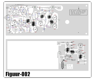
Simple fm transmitter for the experiment. This designation may be appropriate to call this series, because rangkaianya very simple and suitable for learning / beginners. and preferably when assembling, which assembled its first part oscilator. then we try it first. if able to function normally, we can proceed to the next level up to the booster.
Subscribe to:
Posts (Atom)
