Friday, August 15, 2014
Browse »
home »
basic
»
design
»
of
»
power
»
supply
»
the
»
unit
»
THE BASIC OF POWER SUPPLY UNIT DESIGN


Basic of Power Supply - Full Wave Rectifier with Capacitor


Waveform Sinus

Symmetric Power Supply Unit with Full Wave Rectifier


THE BASIC OF POWER SUPPLY UNIT DESIGN
This page is for enthusiasts in the electronics field or for those who need a power supply to power household appliances. This page examines the basic electronics, especially the Power Supply Unit (PSU)
All electronic equipment will not be able to turn on / work without electricity flowing through the system of electronic diagram. Every electronic appliance in our homes, all must relate to electricity, but there are limits to the required voltage. Let us observe the air conditioner in our house. Let us observe the air conditioner in our house. To turn on the compressor and blower, they require electricity from the house, but there are parts of the processor of electronic sensors on the air conditioner only requires a voltage of only 12 volts and 5V. This is done by the method of step-down voltage of 110VAC or 220VAC to 12 Volt DC and 5VDC. The modern system of Power Supply in Air Conditioning has been using the Schematic Power Supply (Switching Power Supply), in which the use of transformers is very small but large enough generated power. Examples of other equipment that requires a Power Supply is a device to charge your phone battery. In a charger for mobile phones requires a 5VDC voltage with less power. You can build a simple Power Supply of the schema shown here.
Basic knowledge of Power Supply Unit (PSU)
In simple PSU equipment, power is supplied through the AC (Alternate Current) input voltage and will be converted into DC voltage with the proper voltage value, this requires high stabilization and avoid distortion wrinkle home electrical pulses through filtering at the output of the DC (Direct Current). As filtering on the DC output is generated and used Capacitor and Electrolytic or Tantalum Capacitor. One day, you will know how important the use of regulators to produce a stable output voltage. The regulator consists of IC 78XX Regulator and other electronics device use.
Simple Basic of Power Supply
The diagram below shows about a simple Power Supply, which is divided into; Half Wave Rectifier and Full Wave Rectifier along with sine wave shape it looks.
Simple Basic of Power Supply
The diagram below shows about a simple Power Supply, which is divided into; Half Wave Rectifier and Full Wave Rectifier along with sine wave shape it looks.


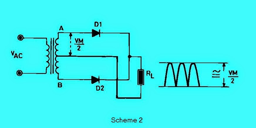
In Scheme 1 and Scheme 2 shows a simple schema rectifier - Scheme 1 is Half Wave Rectifier Circuit diagram, Scheme 2 Full Wave Rectifier Output schema diagram.
In the basic configuration is the peak voltage equal to the peak value of the AC voltage supplied by the transformer secondary wire windings. For most applications, the output ripple is generated by the schema schematic in Figure Scheme 1 and Scheme 2 is too high. But suppose for a particular use to drive a small motor or a lamp has been able to work pretty well.
Basic of Power Supply - Full Wave Rectifier with Capacitor


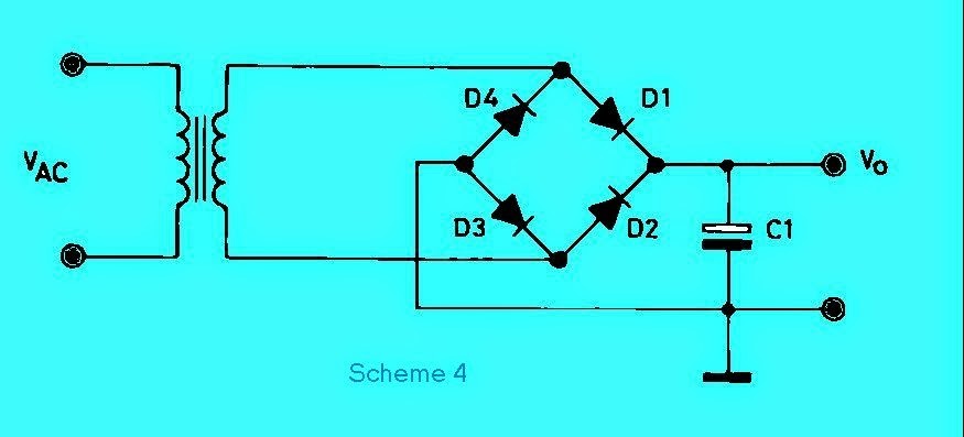
Scheme 3 and Scheme 4 had shown two classic diagram which is used to obtain continuous voltage from an alternating voltage. Scheme 3 diagram using Central Transformer (CT) knocked in two rectifier diodes while the Figure 4 schema uses a simple transformer and four rectifier diodes. Filter capacitor C1 after the diode rectifier is added to increase the output voltage waveform.
Waveform Sinus

Part b-c is a straight line. During this time is that the filter capacitor supplies the load current. The slope of this line increases with increasing current, the point of bringing C lower. As a result, the diode conduction time (c d) increases, increasing the ripple. With zero loads current DC output voltage equal to the peak value of the rectified AC voltage.
Symmetric Power Supply Unit with Full Wave Rectifier

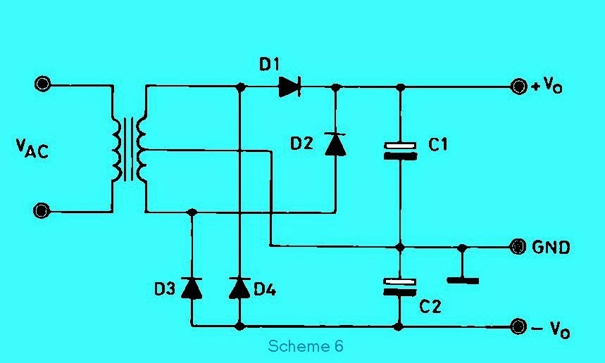
Scheme 6 shows how to get the positive and negative outputs with Common (0V). Ripple voltage value obtained is directly proportional to the load current and inversely proportional to the value of the filter capacitor. Both capacitors should be worth the same. In the schema diagram is intended performance of the device such as an audio amplifier (OP AMP). But it must be coupled 78xx and 79xx combination for increased stability and to eliminate excessive hum.

There are several schemes of power supply contained here. let you see that there is a sidebar on the left to become knowledge for you.
Subscribe to:
Post Comments (Atom)
This is such a great resource that you are providing and you give it away for free. I love seeing blog that understand the value. Im glad to have found this post as its such an interesting one! I am always on the lookout for quality posts and articles so i suppose im lucky to have found this! I hope you will be adding more in the future... http://www.acs-advancedcooling.com/
ReplyDeleteThat seems, by all accounts, to be fantastic anyway i am still not very beyond any doubt that I like it. At any rate will look significantly more into it and choose by and by! air duct cleaning
ReplyDeleteThis comment has been removed by the author.
ReplyDeleteOur company uses the most experienced and skilled repair professionals around. We’re licensed, bonded and fully insured. here is their website https://euappliancerepair.com/
ReplyDelete